Learn when riser clamps are employed in fire sprinkler systems
Riser clamps support the weight of vertical runs of pipe—and water-filled riser pipe in fire sprinkler systems is heavy. Installers have to support that load, and they often can’t rely upon pipe hangers to take the weight of horizontal mains AND the riser. That’s where riser clamps come in.
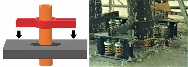
Riser clamps transfer the axial or vertical load of the riser to the building structure, and this typically happens at floor penetrations. The clamp sits on the edges of the floor penetration, placing the weight of the pipe on the slab or another structural member.
But there are also other applications for these devices. In this article, we explain the rules in the 2019 edition of NFPA 13: Standard for the Installation of Sprinkler Systems, including:
- The basics of riser clamp installation
- The placement of riser clamps along the pipe
- When and why to put a clamp under a floor penetration
Shop riser clamps on our website. We have clamps for 2-½ in. pipe, 4 in. pipe, and 6 in. pipe. For custom sizes up to 12 in., call (888) 361-6662 or send us an email.
Pipe riser clamp basics
NFPA 13 gives basic guidelines for supporting vertical pipe. It details the proper installation of riser clamps and explains when and how hanger rods may be used instead.
Riser clamp installation—surface-to-surface engagement
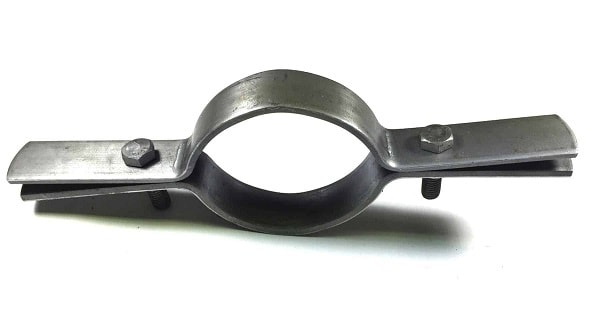
For riser clamp installation, the name of the game is surface-to-surface engagement. Riser clamps take the pipe’s load through friction. The full inside surface of a riser clamp must be held firmly against the pipe’s surface by the clamp’s bolts. Otherwise, slippage may occur. The NFPA 13 Handbook explains that “To adequately support a riser, the full surface of a clamp must bear against the surface of the pipe….”
There are several practical effects of this. First, as section 17.4.5.2 of NFPA 13 specifies, clamps that hold pipe with set screws should not be used, as set screws can’t create enough friction. Second, it’s essential to use a correctly sized clamp. If a clamp is too big or too small, surface-to-surface engagement can’t be achieved. Finally, a riser clamp must be tightened to the proper torque to generate sufficient friction.
In some applications, shear lugs (small pieces of metal) are welded to the pipe, eliminating friction as the load-transfer method. The lugs sit on the riser clamp, and the riser clamp rests on the floor penetration. This method is more labor-intensive, however. NFPA 13 exclusively discusses the frictional approach but does not explicitly prohibit (or mention at all) the use of shear lugs to transfer load.
Riser clamp installation—the clamp is fastened to the structure
Riser clamps transfer the load of riser pipe to the building by interfacing with a structural member. Often, this is done by letting the riser clamp sit on the edges of a slab penetration. In effect, the hole in the slab acts as the hanger for the pipe. NFPA 13 says:
17.1.7.3 Holes through solid structural members shall be permitted to serve as hangers for the support of system piping, provided such holes are permitted by applicable building codes and the spacing and support provisions for hangers of this standard are satisfied.

Besides the slab, riser clamps may also be secured to the building structure by other means. For instance, NFPA 13 says that pipe hangers holding attached horizontal runs of pipe can also be used to bear the load of the riser (17.4.5.1) if they are within 24 in. of the riser centerline. Naturally, the hanger assembly, in this case, should be rated for the combined load.
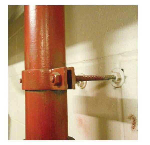
Alternatively, riser clamps can be fastened to walls. However, hanger rods in the horizontal position may not be used for this purpose. A hanger rod handles tension along its axis, but it can’t handle torque. NFPA 13 explains the practical consequences of this:
A.17.2.1.3(1) Hanger rods are intended only to be loaded axially (along the rod). Lateral loads can result in bending, weakening, and even breaking of the rod.
Thus, section 17.4.5.3 of NFPA 13 specifies that riser clamps attached to walls with horizontal hanger rods may not support the weight of risers. But they can be used (A.17.4.5.3) to establish a riser’s horizontal position.

Placement in multistory buildings
A tall riser in a multistory building needs more than one point of support. But where should these supports be placed? NFPA 13 gives simple guidance (17.4.5.4.1) for where riser clamps or other riser supports should be located:
- At the lowest level of the building
- At the top of the riser
- Alternate floors in between
- Above and below every horizontal offset of the riser
Placing a riser support at the lowest building level can be complicated. For instance, not all risers start at ground level. Also, some risers are immediately offset. In both cases, NFPA 13 permits (17.4.5.4.4) the first ceiling penetration of the riser to serve as the first point of riser support.
It might seem redundant to install riser supports at the first ceiling penetration when the base of the riser rests on the ground. NFPA 13 agrees (17.4.5.4.3), saying that “Where risers are supported from the ground, the ground support shall constitute the first level of riser support.”
Finally, not all levels of a building are the same height. Placing a support on each alternate floor is a generally useful rule. However, if this rule is followed despite exceptionally high ceilings, one riser clamp can be left supporting a huge load. To avoid overloading riser supports, NPFA 13 adds this (17.4.5.5) caveat: “Distance between supports for risers shall not exceed 25 ft (7.6 m).”
When and why to put riser clamps under a ceiling penetration?
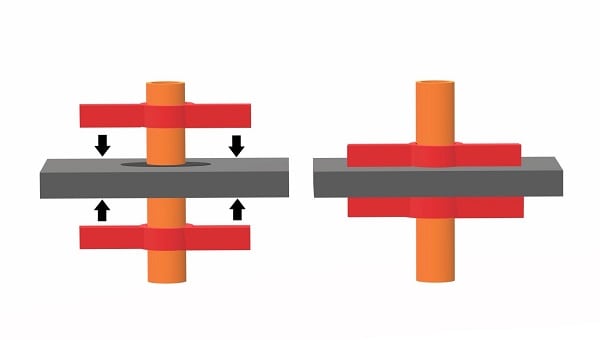
Riser clamps normally rest on top of penetrations in a structural member so that the weight of the riser is transferred to the structure. However, sometimes they are needed below the structural penetration—not to hold weight, but to prevent upward movement permitted by flexible couplings. NFPA 13 says the following:
17.4.5.4.2 Supports above the lowest level shall also restrain the pipe to prevent movement by an upward thrust where flexible fittings are used.
A.17.4.5.4.2 The restraint required by 17.4.5.4.2 is needed to prevent accumulated vertical movement when the riser is pressurized. Restraint is generally provided by use of a riser clamp at the underside of a flood slab.
The thrust referred to here is hydraulic thrust, which is a force that occurs in pipes when flowing water encounters a change in direction or a reduction in size. The momentum of the water is passed on to the pipes, which may move if not properly anchored.
A flexible coupling is a type of pipe fitting that joins two pieces of pipe but still allows some lateral and axial movement at the joint. In other words, the flexible couplings let the pipes flex side-to-side and separate a little without losing their seal. Flexible couplings are an important part of seismic design for pipe systems. Read more about their use in our article on flexibility and seismic protection for fire sprinkler systems.
Among other locations, buildings that require seismic design likely have flexible couplings installed at the top and bottom of risers and above and below floor penetrations. Each of these flexible couplings allows the riser to expand vertically when it is pressurized.

To prevent this vertical movement caused by thrust, risers with flexible couplings have to be restrained. This is usually accomplished with riser clamps placed under the floor penetration. These restraints are needed at the same places that riser clamps bear weight. The effect is that the slab is sandwiched between two risers.
Riser clamps support the weight of riser pipes
Let’s run down a summary of the considerations: Riser clamps hold the weight of riser pipe as it runs vertically through the building. They attach frictionally to the pipe using bolts and transfer the pipe’s weight to the building’s structure. Commonly, the arms of the riser clamp simply sit on the edges of a slab penetration, but a clamp may also be secured to the wall. Instead of using these devices, pipe hangers on horizontal runs of pipe may also support the riser, provided they are within 24 in. of its centerline.
Knowing where NFPA 13 requires riser clamps for fire sprinkler risers is easy. Make sure they aren’t more than 25 ft. apart and put them in the following places:
- At the lowest level
- At the top of the riser
- At alternating floors between the top and bottom of the riser
- At the top and bottom of riser offsets
To prevent vertical movement of the riser when flexible fittings are used, riser clamps can also be installed underneath a slab penetration.
Get all the riser clamps you need on our website. We have clamps for 2-½ in. pipe, 4 in. pipe, and 6 in. pipe.
For custom sizes up 12 in., call us at (888) 361-6662 or send us an email.
This blog was originally posted at blog.qrfs.com.


Does the clamp go on th plywood or above the Jip Board
Christopher – For system application questions like this, you can try our Ask a Fire Pro service. Click the link to submit your question with some information about your building, and a fire protection professional will provide an answer based on standards and codes. Our pros include AHJs, contractors, engineers, and code experts with 150+ years of combined experience!