
The ‘what and where’ of hydraulic design information signs and a step-by-step NFPA 13 example
Hydraulically calculated fire sprinkler systems, which are the vast majority of systems, require at least one and sometimes more hydraulic design information signs.
These signs provide crucial information about a system’s design parameters. They’re vital because they often serve as the only source of these specs when initial plans are lost over time, or maintenance or modifications require this information.
This guide covers:
- What are hydraulically calculated fire sprinkler systems and hydraulic design information signs?
- The NFPA requirements for hydraulic design information signs
- Explaining NFPA 13’s example hydraulic information sign exhibit:
What are hydraulically calculated fire sprinkler systems and a hydraulic design information signs?
Fire sprinkler systems can be designed in two overarching ways: the older pipe schedule method and the now-dominant hydraulic method.
- The pipe schedule method determines a building’s hazard classification or contents, the water supply’s quantity and duration, and the position and density of fire sprinklers in the system, followed by choosing “the pipe size [diameter] needed to” deliver enough water to “the sprinklers on the branch lines.”
- The hydraulic method assesses hazard levels, contents, the water supply, pipe friction, and other specs to mathematically calculate and “fulfill the specified sprinkler density operating over a selected area of application in a fairly uniform manner.” These selected areas are known as design areas. You can read more about the basic steps in fire sprinkler system design in our previous blog.
Pipe-schedule systems have fallen out of favor since the 1980s, and NFPA 13: Standard for the Installation Systems only allows them for new systems or extensions of existing systems in specific cases detailed in section 19.2.2.3 (2022 edition). Regardless, in practice, pipe schedule isn’t used much, as NFPA 13 details in some “FAQ” text:
The pipe schedule method is an acceptable method in all cases for light and ordinary hazard classifications. Its application, however, is not that common because the hydraulic method typically results in more economical systems. […] Eventually, the pipe schedule method might not be used at all.
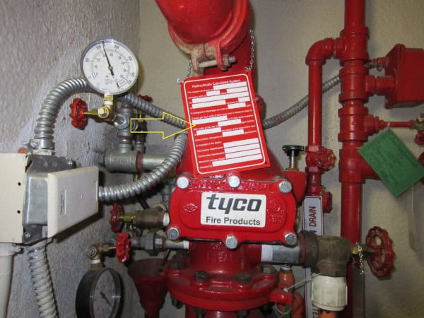
Thus, modern fire sprinkler systems are hydraulically designed systems that need hydraulic design information signs. This marker, also known as a “hydraulic calc plate,” serves important purposes, as NFPA 13 explains:
As-built drawings often become lost or misplaced over time. By keeping a permanent record of the design parameters attached to the system riser, […] it is much easier and less costly to perform future modifications or work on the system. The information contained on such a nameplate is of vital importance in assessing the ability of the system to control fires as the building’s occupancy changes or the water supply’s strength deteriorates.
In addition to supporting any system maintenance, the latter part of NFPA’s explanation deserves more attention.
Often, individuals purchase existing buildings with sprinkler systems and repurpose these structures, or their use and contents otherwise change over time. If a new situation increases the building’s hazard level (say, by storing contents with a more significant fire load), then the existing sprinkler system will be inadequate and need revision. The hydraulic sign provides critical info that makes this assessment easier, especially when the system’s original plans go missing.
The NFPA requirements for hydraulic design information signs
NFPA 13 stipulates that these signs must be present and where, what they must be made of, and how they’re secured in Chapter 29 (some emphasis added):
From the 2022 edition of NFPA 13
29.4.1 The installing contractor shall identify a hydraulically designed sprinkler system with a permanently marked weatherproof metal or rigid plastic sign secured with corrosion-resistant wire, chain, or other approved means.
29.4.2 Such signs shall be placed at every system riser, floor control assembly, alarm valve, dry pipe valve, preaction valve, or deluge valve supplying the corresponding hydraulically designed area unless the AHJ approves an alternate location.
A key concept in the bolded text is that each “system” needs a sign on its appropriate equipment. Very large and/or tall buildings and those with sections storing materials that create different hazard levels may require multiple “systems” and different calculated design areas. But while each location listed above needs a sign, according to the rules, information with their specific hydraulic-calculation info on the separate signs might not be necessary.
If a building is fairly uniform—similar fire protection demands and the same pipe arrangement and sizing on every floor in a multi-story building, for example—then the most demanding design area, typically on the top floor, is often the one that matters. Each sign placed at every floor control assembly could repeat this most demanding hydraulic design area info, which indicates all the lower floors’ fire sprinklers can also handle those needs.
However, NFPA 13 isn’t particularly clear on this point, there is some confusion about it, and different authorities having jurisdiction (AHJs) who enforce the rules may want different things. In addition, the requirements of where to put signs expanded in the 2022 edition of NFPA 13.
We’ll explain some scenarios calling for different signs and calculations in the “Location” section later in this blog. However, a recent TechNotes email from the ever-helpful National Fire Sprinkler Association (NFSA) explains some of this issue:
The required location of the hydraulic data sign in different NFPA 13 editions has caused confusion. In the 2013 – 2019 editions, the sign was required to be located at the alarm valve, dry pipe valve, etc. of the corresponding design area (2013, Section 25.5.1). In the 2022 edition, the text changed, to have the sign placed at every system riser, floor control assembly, alarm valve, etc. (2022, Section 29.4.2). The 2022 edition also added the AHJ can be consulted on sign specifics, so, he or she may exempt additional signs. Here could be an example if the water supply, design, hazard was the same, the AHJ may permit the exclusion of the sign or permit redundant signs at each floor.
Here’s what must be on the sign, though not all of the seven items apply to every system:
From the 2022 edition of NFPA 13
29.4.3 The sign shall include the following information:
(1) Location of the design area or areas
(2) Size (area) of or number of sprinklers in the design area
(3) Discharge densities over the design area or areas
(4) Required flow and residual pressure demand at the base of the riser or fire pump where applicable
(5) Occupancy classification or commodity classification and maximum permitted storage height and configuration
(6) Hose stream allowance included in addition to the sprinkler demand
(7) Name of the installing contractor
Now, let’s take a look at an example sign.
Explaining NFPA 13’s example hydraulic information sign:
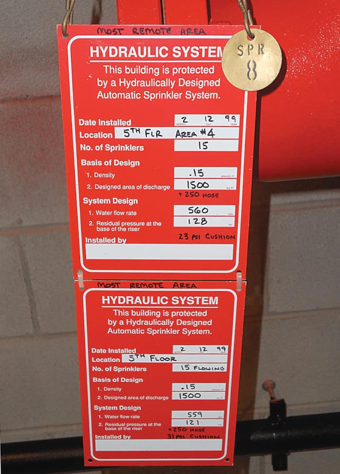
Exhibit 29.3 in NFPA 13 (2022) below shows a filled-out “typical hydraulic nameplate:”
Let’s go over these items in detail:
This is pretty self-explanatory—it’s the date the system was installed. Check!
Again, some buildings have multiple “systems” and/or multiple design areas, and a sign must be at “every system riser, floor control assembly, alarm valve, dry pipe valve, preaction valve, or deluge valve.”
For example, there may be multiple system risers to address different conditions in a building (e.g., a wet and dry system) or different floor control valve assemblies when a structure becomes large enough to make taking all the fire sprinklers offline at once (e.g., for maintenance) a bad idea.
NFPA 13 requires floor control valve assemblies for new systems in buildings exceeding two stories unless they are under a specific square footage (usually less than 52,000 for light or ordinary hazard occupancies (NFPA 13: 16.9.10.1/4.4.1)). These assemblies separate the water flow to floors via control valves. Each assembly has a distinct control valve, flow switch, and gauge, making it, in essence, considered a distinct system theoretically with at least one distinct design area.
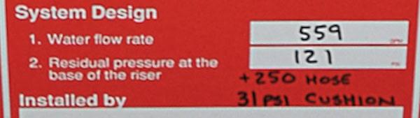
In NFPA 13’s sign example, there are two design areas indicated by these signs: “5th FLR” and “5th FLR AREA #4:”
However, the only difference in the numbers is that “AREA #4” has a slightly higher flow rate and residual pressure. We don’t have enough context about the building to know the reasons for these signs, and there may be more off-camera. Regardless, there is a head-scratching element to these example signs.
Again, a design area usually indicates the most challenging area to protect. However, a few reasons to have multiple design areas (on multiple signs) are:
- A separate design area within this ‘system’ has unique hazards. (Frank from accounting is storing cans of gasoline in the breakroom again! That’s a bad example, but you get the gist.)
- A system designer changed the pipe size feeding one area (often to lower cost), requiring separate calculations.
- The most demanding area doesn’t reflect most of the space on the floor, so it’s a good idea to list calculations for multiple design areas.
- Separate design areas have unique pressure or flow demands—not both metrics being higher in one area (which would clearly make one design area the most challenging.)
The last two reasons are the most potentially relevant ones to NFPA 13’s example sign.
1. One scenario calling for multiple signs with different numbers is that the most demanding design area doesn’t reflect most of the space on the floor.
Picture an office building where most of a floor is 50,000 square feet of cubicles, making it a light hazard occupancy classification. However, a 2,000-square-foot kitchen near the sprinkler riser is ordinary hazard 1. The design areas and numbers would be different, and the kitchen would technically be the most demanding design.
However, it can make sense to have both sets of hydraulic calculations listed on two signs, since the kitchen doesn’t reflect most of the floor’s environment and fire protection needs.

2. Another scenario is when two design areas have unique pressure or flow demands—not both.
For example, say that the design area of a specific architectural feature on the 5th floor is more elevated but smaller; it might require more pressure (due to gravity) but lesser flow (with fewer sprinklers). In that case, two signs and design areas would make sense. One of the numbers on each sign (pressure or flow) would be higher (more demanding) for each area, requiring two signs.
However, neither of these situations seems to apply in NFPA 13’s sign example.
Both signs have the same “Basis of design” indicating the same hazard and fire protection needs. And “5th FLR AREA #4” seems to be clearly (if slightly) the most demanding area in terms of pressure and flow.
So, without knowing additional context about the building, this floor control assembly might only need one sign with the higher numbers. However, an AHJ may have required two, or the designer/installer decided to be extra informative and careful.
Number of sprinklers and basis of design
Again, system designers calculate a design area by assessing what’s needed to ensure the water supply can handle “the most demanding situation faced by the system.”
Often, due to distance and gravity, this design area is the farthest/highest specific area from the water supply, such as the opposite corner of a building’s top floor. This design area will have the greatest flow and pressure demands and require sufficient sprinklers with the right K-factors and coverage specs to deliver enough water.
Putting aside “special design areas” for the moment, designers commonly use one of these methods:
- The room design method is based on the number of sprinklers in a room, assuming all of them will open at once to provide adequate water and coverage for the design area. The definition of a “room” is flexible, however, and can include hallways or adjoining spaces. NFPA 13 states the room design method is better suited for “highly compartmented” buildings.
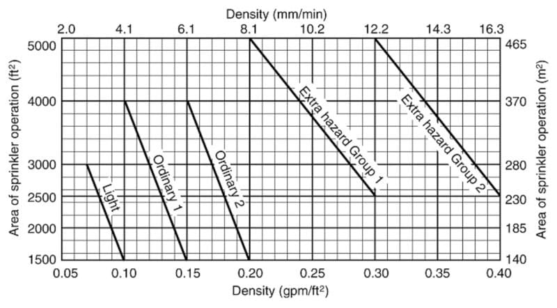
- The density/area method, more commonly used, is based on achieving a minimum discharge density (gallons per minute (GPM) per square foot) based on the specific hazard level and area of sprinkler operation (square feet). It’s calculated based on “Density/Area Curves” outlined in NFPA 13.
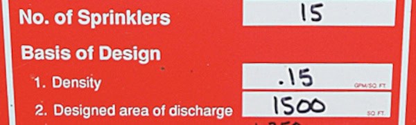
1. We see that the signs have spots for the information required for either the room design method or the density/area method of hydraulic calculations.
2. In this case, the design basis of the system is 0.15 gpm/square foot for a 1,500-square-foot design area. Looking at NFPA 13’s Density/Area Curves tells us it’s an Ordinary Hazard 1 occupancy classification (see the red circle below):
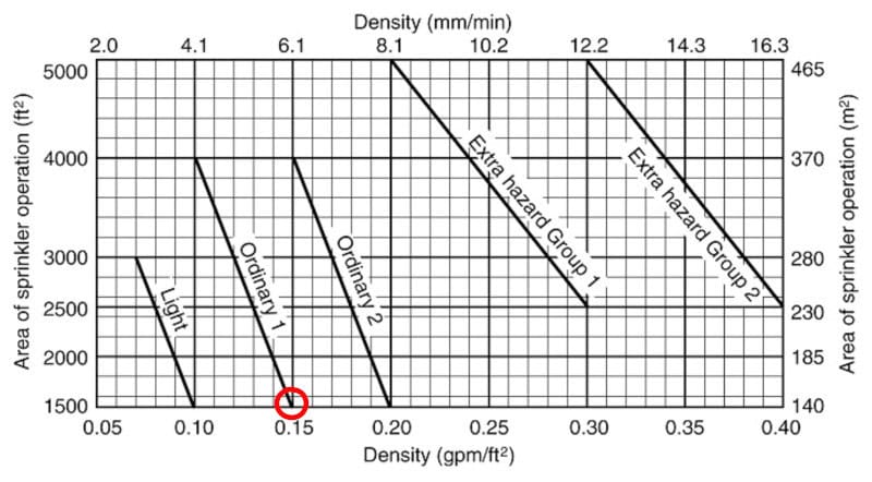
Again, this information on the sign can be very important. Let’s say the building’s use and contents change, bumping up the occupancy classification to ordinary hazard 2 instead of ordinary hazard 1. In that case, a design density of 0.15 gpm/square foot would not be sufficient for a 1,500-square-foot design area—the density would need to increase to 0.20 gpm/square foot. If no one makes this change, a fire could overwhelm the sprinklers and their supply.
A hydraulic design information sign allows fire protection pros and AHJs to spot any design deficiencies at a glance, in concert with other information about the building. And again, it may be crucial data to have on hand if the building changes and the original system plans are lost.
Water flow rate and residual pressure at the base of the riser
The water flow rate indicates the required flow (how much water flows and how fast in GPM) when the system activates. The residual pressure at the base of the riser (or fire pump) tells you how much pressure remains in the pipe when all the sprinklers in the design area have been activated.
For example, let’s say that a wet sprinkler system has a normal static pressure of 90 PSI when water isn’t moving. The gauge on the system side of the water supply by the riser may read around 90 PSI when no sprinklers are activated.
Designers calculate the water and pressure demands of all the sprinklers in a design area. Let’s assume that when eight sprinklers flow in a design area, their activation will bleed off 40 PSI of pressure. Our system’s static pressure of 90 PSI minus 40 PSI would equal an estimated 50 PSI of residual pressure left over at the base of the riser.
This number is essential because the sprinkler system must have enough static and residual pressure to meet the demand of the design area when the sprinklers go off. And if the system can handle these requirements for the most demanding design area, it can typically handle less demanding areas, too.
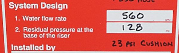
The residual pressure numbers will increase for larger and taller buildings. For example, compared to the sample 40 PSI residual pressure we just discussed, the number is much higher in NFPA’s example sign for a building of at least five floors:
Again, it’s useful to understand these system specs and whether they are adequate for the property’s current hazard level, contents, and use.
Don’t equate “hose stream allowance” with “hose” and “cushion” in NFPA’s sign example
What about the handwritten “cushion” and “hose” numbers on NFPA 13’s example sign? This hydraulic plate has some letters and numbers written in black permanent marker; here’s the additional info on the “5th FLR” sign:
Remember, among the items a sign must have in section 29.4.3 of NFPA 13—if applicable to the system—is a “Hose stream allowance included in addition to the sprinkler demand.” However, what this requirement intends to cover is probably not what’s written on the example sign, according to an NFPA committee member consulted by QRFS.
A hose stream allowance indicates that an internal hose connection(s), either attached to a sprinkler system or in a combination sprinkler/standpipe system with hose stations, is in the building. This creates the need for an “allowance” for the system to have enough pressure and flow to accommodate the additional demand from the hose connections beyond the sprinklers.
In the example sign’s case, it indicates “+250 GPM” for a hose, but this high flow demand likely indicates an external hose that firefighters would use. An internal hose GPM number would be lower (50 or 100 GPM). In addition, the extra demand for internal hoses would be baked into the overall flow rate and pressure numbers on the sign.
The written “cushion” of 31 PSI seems to have nothing to do with the hose number, and it is also not required on the sign. The author is just being helpful by providing additional information. Designers take flow measurements of the known characteristics of the water source at the street (e.g., from a flow-tested hydrant). And many wise system designers offer a little leeway between the pressure from the water’s source and what’s needed at the riser.
So, that 31 PSI of cushion on the 5th FLR sign likely means that while the system design area only needs 121 PSI to meet the density demand of 0.15 gpm/square foot, there is actually 152 PSI coming in off the street before it hits the riser, based on known measurements.
Too much pressure can be a challenge and require pressure-restricting valves at certain points in the system, but a bit of extra pressure is a sensible buffer. It helps ensure that there will always be enough PSI to handle a fire—barring unforeseen circumstances, like a break in municipal water infrastructure.
What’s missing on the sign: “Installed by” and the occupancy classification
The only other wrinkles with NFPA 13’s example sign are two missing but required pieces of info:
(5) Occupancy classification or commodity classification and maximum permitted storage height and configuration
(7) Name of the installing contractor
The “Installed by” section is blank. Tsk tsk—though it may have been added later or withheld in the image for privacy concerns. This information is helpful when someone needs more information about the system, including copies of original plans.
“Commodity classification and maximum storage height and configuration” likely don’t apply in this building (e.g., not a storage facility), but the “occupancy classification” does, and the sign doesn’t spell it out.
Fortunately, that’s not a big deal because we can figure out the occupancy classification from the “Basis of design” numbers: 0.15 gpm/square foot at 1,500 square feet indicates an ordinary hazard 1 occupancy classification.
Hydraulic design information signs are always helpful and may be crucial!
NFPA 13 and NFPA 25: Standard for the Inspection, Testing, and Maintenance of Water-Based Fire Protection Systems require hydraulic calc plates for very good reasons.
They allow pros to quickly assess whether a design is inadequate. Often, this happens when a building’s use and contents have changed enough to need a new hazard level, meaning a fire could overwhelm the current fire sprinkler system.
In addition, fire sprinkler systems last decades—plenty of time for the original design plans to go missing and installing contractors to cease operations. A simple sign communicates a lot of vital info quickly.
Make sure your system (or the ones you work on) has accurate hydraulic design information signs where they need to be. If there is any confusion, work with your local AHJ to determine what’s necessary. And be sure to use a permanent marker to fill in any additional details required by NFPA 13.
QRFS carries hydraulic calc plates and a variety of other essential sprinkler signs.
If you have questions or need help placing an order, contact us at support@qrfs.com or 888-361-6662.
This blog was originally posted at blog.qrfs.com.