The durable signage required by NFPA 13 provides critical system information, including the locations of key components
The National Fire Protection Association (NFPA) has complex requirements for labeling the components of a fire sprinkler system. NFPA 13: Standard for the Installation of Sprinkler Systems (2022 edition) contains various sections detailing the different signs required for a system, with many more specific information requirements for each sign. Despite this guidance, some contractors and building owners fail to install or account for all of these markings, which can cause problems beyond a code violation. Missing fire sprinkler signs can result in system damage, liability, or the worst possible outcome: a sprinkler system that fails in the event of an emergency.
In an article at Sprinkler Age, fire protection engineer John Denhardt wrote about some of the signage problems he witnessed as a fire safety contractor, including one that resulted in “over $500,000 in property damage for one property owner.” The culprit? A missing sign should have indicated the presence and location of a second control valve. “In an emergency, the control valves were not able to be turned off in a timely manner and no one on-site knew the location of the second control valve.”
Half a million dollars in damage may have been prevented by investing in a sign that costs a few dollars. Clearly, it’s a good investment.
This article examines the requirements for fire sprinkler signs according to NFPA 13, simplifying the subject for contractors and building owners.
Are you looking to buy signs to mark your fire protection system? If so, feel free to skip directly to our selection of standard fire signs.
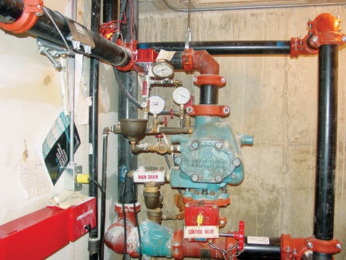
Most fire sprinkler system valves must be identified with metal or rigid plastic signs
Section 16.9.11 of NFPA 13 (2022 edition) stipulates sign requirements for valves, while section 16.9.3 expands on the guidance for control valves.
From the 2022 Edition of NFPA 13
16.9.11* Identification of Valves.
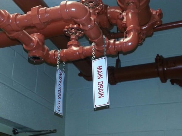
16.9.11.1 All control, drain, venting, and test connection valves shall be provided with permanently marked weather-proof metal or rigid plastic identification signs.
16.9.11.2 The identification sign shall be secured with corrosion-resistant wire, chain, or other approved means.
16.9.11.3 The control valve sign shall identify the portion of the building served.
16.9.11.3.1* Systems that have more than one control valve that must be closed to work on a system or space shall have a sign referring to existence and location of other valves.
16.9.3* Control Valves.
16.9.3.5 Control Valve Identification. Identification signs shall be provided at each valve to indicate its function and what it controls.
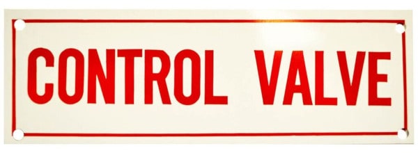
Control valve signs
As the name implies, control valves control the supply of water to an automatic fire sprinkler. And for the system to work in an emergency, they must remain open.
Closed control valves are the leading cause of sprinkler failure during a fire; if a valve is shut off during testing or installation and a contractor fails to find and reopen it, the sprinkler won’t perform. If sprinklers improperly activate or components are improperly installed, and someone needs to cut off the water supply, failing to find a control valve could result in damage to the system and building. Finally, if a fire has been controlled and the sprinklers need to be stopped to minimize water damage, it’s essential to know where every control valve is located and what portion of the building it serves.
Drain valve signs
A standard interpretation of NFPA’s requirements for drain valves is that a sign needs to identify the main drain valve assembly, which serves to drain water from the system and provides a way to measure water flow during the main drain test. Knowing where the system drains is essential for fire sprinklers that need to be taken out of service for any period of time (for testing or repair), or for systems that must be drained to avoid damage from water freezing in the pipes.

For a deep dive into draining fire sprinklers, check out our article on Draining a Fire Sprinkler System.
In addition, NFPA 13 adds an additional sign requirement for dry pipe or preaction sprinkler systems:
From the 2022 Edition of NFPA 13
16.10.5.3.7 Systems with low point drains shall have a sign at the dry pipe or preaction valve indicating the number of low point drains and the location of each individual drain.
The Sprinkler Age article mentioned earlier notes that many contractors fail to include this sign, and details an example of the consequences:
Lack of providing this sign has caused numerous installing contractors to lose legal claims that were brought against them when systems experienced freeze damage. In one case that I personally know, a maintenance crew drained all the low points that they saw but the system still experienced pipe damaged due to freezing. There were seven low points but two of them were not obvious. The low points were shown on the “as-built” drawings, but because the required signage was not provided, the installing contractor was still found liable.
Venting valves signs
Venting valves are used to vent air that is trapped in a wet sprinkler system. Doing so fights corrosion in the interior of the pipes by reducing the amount of oxygen dissolved in the water, which in turn reduces the chances of blockages or leaks. Some vents are automatic, shutting off when water reaches the vent, whereas others are manual, requiring the valve to be closed after removing excess air. These fire sprinkler system signs ensure that they are identified and closed during normal system operation, and used to vent air when required.
Test connection valve signs
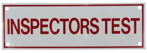
The inspector’s test valve can be opened to assess water flow through the sprinkler riser. These tests are performed for a variety of reasons: ensuring that the water flow alarm works, testing the opening of a dry-pipe or pre-action valve, or assessing how long it takes for water to arrive at an average sprinkler head at system working pressure. The valve should be marked so that it can be easily found to conduct a test and fully closed when not in use.
Anti-freeze sprinkler system signs
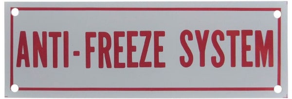
Antifreeze systems need specific signs explaining the location of systems that are remote from the riser, as well as the specifications of the antifreeze used in them.
From the 2022 Edition of NFPA 13
8.6.1.4 Where antifreeze systems are remote from the system riser, a placard shall be mounted on the system riser that indicates the number and location of all remote antifreeze systems supplied by that riser.
8.6.1.5 A placard shall be placed on the antifreeze system main valve that indicates the manufacture type and brand of the antifreeze solution, the minimum use temperature of the antifreeze solution used, and the volume of the antifreeze solution used in the system.
The latter requirement is needed because antifreeze solutions with too much glycerin or propylene glycol relative to water were found to ignite and actually feed a fire. NFPA now requires antifreeze solutions to “be listed for use in sprinkler system.” (8.6.2.1) The development, testing, and subsequent listing of safer antifreeze solutions is a relatively new development, and using older, non-listed solutions were phased out as of Sept. 2022. An exception to this listing requirement remains, however:
8.6.2.2 Premixed antifreeze solutions of propylene glycol shall be permitted to be used with ESFR sprinklers where the ESFR sprinklers are listed for such use in a specific application.
In any case, signage detailing the antifreeze used and its specs is still required to ensure safety and compliance with the standard. To read more about flammability issues that caused antifreeze updates, check out our blog: “The Use of Antifreeze in Fire Protection Systems.”
Additional fire sprinkler system signage is required for fire department connections, hydraulic systems, to convey general information, and mark signaling devices
NFPA-compliant fire sprinkler systems require signs marking each connected fire department connection (FDC), and they must include the following information:
- The service design of the FDC
- Which part of the building an FDC serves (if it serves only a portion)
- The “pressure required at the inlets to deliver the greatest system demand” — if the system demand pressure is 150 psi or greater.
From the 2022 Edition of NFPA 13
16.12.5.6 Where a fire department connection services only a portion of a building, a sign shall be attached indicating the portions of the building served.
16.12.5.8.1 Each fire department connection to sprinkler systems shall be designated by a sign having raised or engraved letters at least 1 in. (25 mm) in height on plate or fitting reading service design — for example, AUTOSPKR., OPEN SPKR., AND STANDPIPE.
16.12.5.8.2 A sign shall also indicate the pressure required at the inlets to deliver the greatest system demand.
16.12.5.8.3 The sign required in 16.12.5.8.2 shall not be required where the system demand pressure is less than 150 psi (10.3 bar).
In addition, Section 31.2.7.5 of NFPA 13 requires marine sprinkler systems to have an 18″ × 18″ sign showing the FDC symbol “placed at the connection so that it is in plain sight from the shore access point.”
Hydraulic design information signs
As part of NFPA 13 sprinkler system acceptance requirements, all hydraulically designed sprinkler systems must be appropriately labeled as such “with a permanently marked weatherproof metal or rigid plastic sign secured with corrosion-resistant wire, chain, or other approved means” (29.4.1). These “signs shall be placed at every system riser, floor control assembly, alarm valve, dry pipe valve, preaction valve, or deluge valve supplying the corresponding hydraulically designed area unless the AHJ approves an alternate location.” (29.4.2)
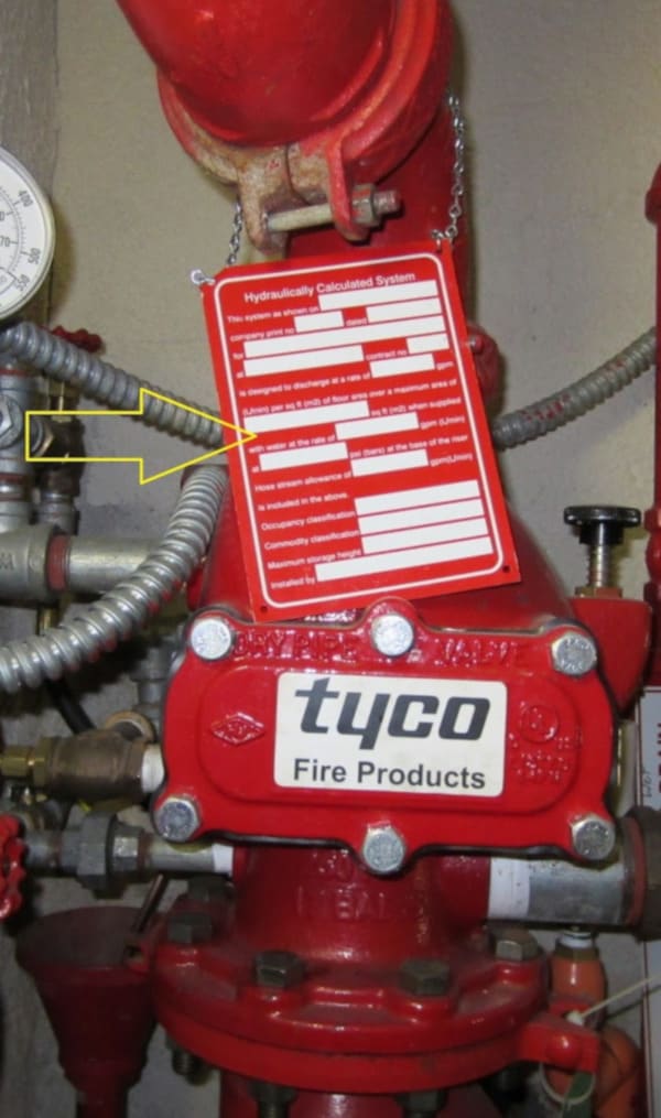
There are two basic designs for a sprinkler system: the older pipe schedule method and the hydraulic design. Pipe schedule requires a specific number of sprinklers to be fed off of a specifically-sized pipe at system pressure, whereas hydraulic systems allow the use of a flexible number of sprinklers based on a certain area’s hazard classification (accounting for the water supply and pressure, pipe size and friction, sprinkler K-factor, and other factors). NFPA restricts the use of pipe schedule systems for new installations, so the vast majority of sprinkler systems will be hydraulically designed and require appropriate signage.
From the 2022 Edition of NFPA 13
29.4.3 The sign shall include the following information:
(1) Location of the design area or areas
(2) Size (area) of or number of sprinklers in the design area
(3) Discharge densities over the design area or areas
(4) Required flow and residual pressure demand at the base of the riser or fire pump where applicable
(5) Occupancy classification or commodity classification and maximum permitted storage height and configuration
(6) Hose stream allowance included in addition to the sprinkler demand
(7) Name of the installing contractor
The main purpose of the hydraulic information sign is to clearly establish the system’s capabilities and what it was designed to handle. As NFPA 13 notes, “Changes of occupancy or commodity could alter the hydraulic demand.” So, for example, a building that changes hands to a business that suddenly starts storing highly flammable items may not have a fire sprinkler system that’s designed to handle its fire protection needs. A hydraulic sign makes this problem after a “change of use” very clear.
Note: as we cover at the end of the next section, NFPA 13 now allows the hydraulic information sign to be combined with the general information sign.
General information signs
All sprinkler systems require a general information sign that details the “system design basis and information relevant to the inspection, testing, and maintenance requirements required by NFPA 25.” [29.6.1]. As with certain other signs, it must be “a permanently marked weather-proof metal or rigid plastic sign, secured with corrosion-resistant wire, chain, or other acceptable means”[29.6.1.1]. The sign must be present at the “system control riser, antifreeze loop, and auxiliary system control valve” [29.6.1.2] and have up to 20 different pieces of information, depending on the specific building and fire sprinkler system.
From the 2022 Edition of NFPA 13
29.6.2 The sign shall include the following information:
(1) Name and location of the facility protected
(2) Occupancy classification
(3) Commodity classification
(4) Presence of high-piled and/or rack storage
(5) Maximum height of storage planned
(6) Aisle width planned
(7) Encapsulation of pallet loads
(8) Presence of solid shelving
(9) Flow test data
(10) Presence of flammable/combustible liquids
(11) Presence of hazardous materials
(12) Presence of other special storage
(13) Location of venting valve
(14) Location of auxiliary drains and low point drains on dry pipe and preaction systems
(15) Original results of main drain flow test
(16) Original results of dry pipe and double interlock preaction valve test
(17) Name of installing contractor or designer
(18) Indication of presence and location of antifreeze or other auxiliary systems
(19) Where injection systems are installed to treat MIC or corrosion, the type of chemical, concentration of the chemical, and where information can be found as to the proper disposal of the chemical
(20) Indication of presence of nitrogen where used to allow for increased C value in dry or preaction system
The hydraulic information sign and the general information sign contain some of the same info and can take up a lot of space, so NFPA 13 now allows one sign serving both purposes:
29.6.3 Combination hydraulic design information and general information shall be permitted.
Signaling System Signs
Finally, if a structure has an outside alarm that indicates the deployment of the fire sprinkler system, the NFPA 13 Appendix says that a sign should be installed “near the device in a conspicuous position” and suggests the following wording: “SPRINKLER FIRE ALARM — WHEN BELL RINGS CALL FIRE DEPARTMENT OR POLICE.” [A.8.17.1]
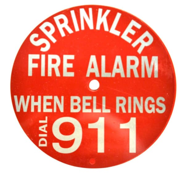
While most fire sprinkler system signs must be metal or plastic, those not covered by NFPA rules may be made from other materials
NFPA 13 is very specific about the physical design of signs that are required for certain areas. All valve signs, hydraulic design signs, and general information signs must be “permanently marked weather-proof metal or rigid plastic identification signs secured with corrosion-resistant wire, chain, or other approved means.” In addition, the sign showing the fire department connection must have “raised or engraved letters at least 1 in. (25 mm) in height on plate or fitting” that spell out the service design of the system. Beyond those specific signs, a fair interpretation of NFPA standards is that any other markings can be decals, stickers, or placards, as long as they are durable and convey the necessary information.
Keep your fire sprinkler system compliant and safe
Making sure a fire sprinkler system is properly marked doesn’t simply keep it compliant with code; identifying crucial components also helps contractors and building owners avoid liability and reduce the risk of system failure during an emergency. At QRFS, we offer a variety of signs, decals, and stickers to help you satisfy NFPA 13 and other safety signage requirements.
Do you have more questions about fire sprinkler system signage? Comment here, call us at +1 (888) 361-6662 or email support@qrfs.com.
This blog was originally published at blog.qrfs.com on December 14, 2017, and updated on December 7, 2022.



Is it required or listed in NFPA to have a “Sprinkler Room” sign on the door leading into the riser room?
Jeff — It’s required by the International Fire Code, an adopted version of which is legally in force in most states. The below reference is in the 2018 (901.4.6.2) and 2021 editions (901.4.7.2):
Marking on access doors. Access doors for automatic sprinkler system riser rooms and fire pump rooms shall be labeled with an approved sign. The lettering shall be in a contrasting color to the background. Letters shall have a minimum height of 2 inches (51 mm) with a minimum stroke of 3/8 inch (10 mm).
We have a 1″ brass drain ball valve that we needed to plug and remove the handle from due to being accessible to students in a school.
Is this valve required to be tagged?
Nick — important: before you plug any valve and removed the handle, it’s essential to consult a fire protection professional. They can determine the best course of action to prevent students from accessing it (potentially. moving it), determine any consequences of not being able to quickly access that plugged valve w/o a handle, and appropriately mark it, if necessary.
are outside Control valves like on Backflows and PIV required to have a control sign ?
NFPA 24 provides guidance on marking post-indicator valves in pits (6.4.4), specifically, and valves overall (below references from 2022 edition):
6.4.4 The location of the valve shall be marked, and the cover of the pit shall be kept free of obstructions.
6.7.1 Identification signs shall be provided at each valve to indicate the valve’s function and the part of the system the valve controls.
6.7.1.1 Identification signs in 6.7.1 shall not be required for underground gate valves with roadway boxes.
If systems need to have a domain/zone map in the sprinkler riser room, what is the nfpa number?
Rick — We’re unsure of the answer to your question, as NFPA 13 does not specify “zone map” rules; if you are referring to the requirement of outlining design areas, that’s section 29.4.3. Any antifreeze portions of the system also must be outlined (8.6.1.4), and control valve signs must indicate the portion of the system served (16.9.11.3).
Question: A building sprinkler system installed in 1966 does not have a hydraulic calculation plate attached to it. But it is uncertain that a sprinkler system installed that long ago could have been designed using the Pipe Schedule system of design. How can one tell what the type of design for a system installed in 1966? If it was a Pipe Schedule system what kind of permanent information would be attached to the sprinkler riser, if any.
Skip — There’s a separate rule/plate for that:
If no signs indicate this, a pro needs to closely evaluate the system.
Thanks for the post. As I understand it though the piping does not need to be red, it can also have sticker saying it is fire water pipe?
Kristofer — Can you please specify what text you are referring to? Pipes in fire sprinkler systems do not have to be red (e.g., CPVC is orange, and steel pipes are usually black), but most signage and markings are done in a red scheme to indicate fire protection. Thanks for reading.