The ongoing tests of standpipes required by NFPA 25
Previously, the blog posts in this series have covered standpipe systems, required maintenance, the components of systems, and testing. This article will break down the maintenance testing requirements for existing standpipe systems defined in NFPA 25: Standard for the Inspection, Testing, and Maintenance of Water-Based Fire Protection Systems. Our goal is to aggregate and contextualize this code for contractors and building owners.
This post is part 5 of a 7 part series on standpipe systems:
Part 1: Fire Protection Standpipe System Overview and Introduction to NFPA 14
Part 2: Standpipe System Components and How to Maintain Them
Part 3: More Standpipe System Components and How to Maintain Them
Part 4: Acceptance Testing and Ongoing System Maintenance
Part 5: Maintenance Testing of Standpipes (Continued)
Part 6: Maintenance Testing for Automatic and Semiautomatic Dry Standpipes
Part 7: Standpipe Signs and Markings
Are you looking to buy components or accessories for your building’s standpipe system? If so, feel free to skip directly to our selection of gauges, pin racks, fire hose reels, butterfly valves, check valves, hydrostatic test pumps, and hose angle valves, or just use the search bar at the top of the page to find what you’re looking for.
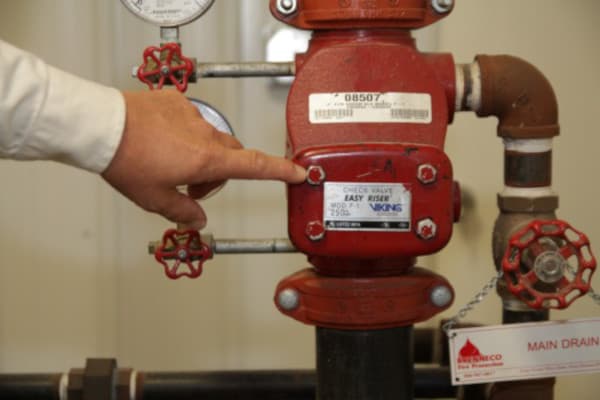
Main drain test
A standpipe system’s main drain is simply an orifice (often a hose connection) located downstream of the water supply and the main control valve. Closing the main control valve and opening the main drain allows the system to be completely drained for maintenance or repair purposes, and NFPA 25 requires the main drain and the piping that leads to it to be tested on an annual or quarterly basis.
From the 2017 Edition of NFPA 25
13.2.5* Main Drain Test. A main drain test shall be conducted annually for each water supply lead-in to a building water-based fire protection system to determine whether there has been a change in the condition of the water supply.
13.2.5.1 Where the lead-in to a building supplies a header or manifold serving multiple systems, a single main drain test shall be permitted.
13.2.5.2 In systems where the sole water supply is through a backflow preventer and/or pressure-reducing valves, the main drain test of at least one system downstream of the device shall be conducted on a quarterly basis.
13.2.5.3 When there is a 10 percent reduction in full flow pressure when compared to the original acceptance test or previously performed tests, the cause of the reduction shall be identified and corrected if necessary.
The test is done to verify that there are no blockages or partially-closed valves between the water supply and the hose connections (at least to the point of the main drain) and to make sure the water supply pressure remains steady. To accomplish the latter, static and residual pressure readings are taken during the test. If you recall from our previous piece, NFPA 14 required a main drain flow test as part of acceptance testing of aboveground pipe (14: 11.5.6.1, 11.5.6.2), stipulating that the static and residual pressures must be recorded during that test. These initial readings serve as a benchmark that new readings are compared to; over time, if the measurements show a large difference in pressure, it could indicate a blockage or other water supply issues.
To be clear, it’s important to compare the current static pressure readings to past static pressure readings and the current residual readings to previous residual readings; any notable swing in one reading – without a similar swing in the other reading – merits investigation. NFPA 25 also specifies that any 10 percent drop in full flow pressure during a new test requires investigation and possible correction.
The above testing is required to be conducted annually unless there is a backflow preventer and/or pressure reducing valves installed between the water supply and the main drain, in which cases the test must be done quarterly. In these cases, the main drain test essentially doubles as a flow test for the backflow preventer, working its springs so they don’t get stuck shut while verifying that pressure-reducing devices are working properly.
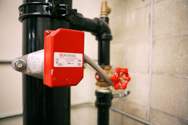
Waterflow alarm test
There are three types of waterflow alarms, each of which is designed to alert building personnel and bystanders to the activation of a fire protection system.
Mechanical waterflow alarms: Water pushes a paddle attached to a hammer that hits a bell after every revolution of the paddle. These alarms require no power source other than the flowing water.
From the 2017 Edition of NFPA 25
13.2.6.1.2 Mechanical waterflow alarm devices shall be tested quarterly.
Vane-type waterflow alarms: These alarms are only used in wet standpipe systems. They feature a paddle that is inserted into the inside of the pipe through its wall. When water flows, the paddle moves and flips a switch that turns on an electrical alarm. The alarm may be set to a delay of up to 90 seconds to ensure that the water continues to flow, thereby limiting false alarms.
Pressure switch waterflow alarms: These alarms use a sensor that detects a change in pressure due to water that is diverted to a small section of test pipe. These can also be set with a delay of up to 90 seconds.
From the 2017 Edition of NFPA 25
13.2.6.2.2 Vane-type, paddle-type, and pressure switch-type waterflow alarm devices shall be tested semiannually.
The exact methodology for testing these alarms depends on whether the systems are wet or dry, as well as whether freezing temperatures will impact the test. But the principle is the same: create water flow to an outlet and see if the alarm is triggered.
From the 2017 Edition of NFPA 25
13.2.6.3 Testing waterflow alarm devices on wet pipe systems shall be accomplished by opening the inspector’s test valve or by using the automated test equipment in accordance with 4.6.6.
N 13.2.6.4 Where freezing weather conditions or other circumstances prohibits the use of the inspector’s test valve, the bypass connection shall be permitted to be used.
N 13.2.6.5 Fire pumps shall not be taken out of service during testing unless constantly attended by qualified personnel, or all impairment procedures contained in Chapter 15 are followed.
N 13.2.6.6* Testing waterflow alarm devices on dry pipe, preaction, or deluge systems shall be accomplished by using the bypass connection.
Gauge tests
In addition to the monthly and quarterly inspection requirements for gauges, they must be tested and/or replaced every 5 years:
From the 2017 Edition of NFPA 25
13.2.7.2* Gauges shall be replaced every 5 years or tested every 5 years by comparison with a calibrated gauge.
N 13.2.7.3 Gauges not accurate to within 3 percent of the full scale shall be recalibrated or replaced.
“Full scale” means the maximum reading of the gauge. Given the hassle and potential man-hours of testing all of the gauges in a system, as well as the relatively low prices of new gauges, simply replacing them at five-year intervals may be the best option.
Supervisory signal device tests
NFPA 25 stipulates that all supervisory signal devices, with the exception of “valve supervisory switches,” must be tested annually.
From the 2017 Edition of NFPA 25
13.2.8.2 Supervisory signal devices shall be tested annually in accordance with the manufacturer’s instructions.
NFPA 72 defines a supervisory signal initiating device as follows:
“An initiating device such as a supervisory switch, water level indicator, or low air pressure switch on a dry-pipe sprinkler system in which the change of state signals an off-normal condition and its restoration to normal of a fire protection or life safety system; or a need for action in connection with guard tours, fire suppression systems or equipment, or maintenance features of related systems.”
NFPA 72 goes on to list “five types of initiating supervisory signals [see Table 7-2.2 Test Methods; Section 13(h)]: control valve switch, high- or low-air pressure switch, room temperature switch, water level switch, and water temperature switch. However, the complete list of supervisory signals goes beyond these five types listed.”
Essentially, anything that sets of an alarm to indicate that the system is not functioning as it should is considered a supervisory signal device and must be tested quarterly. These devices can include water level and temperature alarms for onsite water tanks, building temperature alarms that indicate freezing conditions, and a host of alarms that gauge the readiness of automatic or semiautomatic dry pipe systems or onsite fire pumps.
Testing of control valves and control valve supervisory switches
Control valves must be put through their full range of motion once per year. This means that if a valve is normally open, it will be fully closed and then opened again. A main drain test should be conducted whenever the control valves are tested, so it is wise to coordinate these activities on an annual basis.
From the 2017 Edition of NFPA 25
13.3.3.1 Each control valve shall be operated annually through its full range and returned to its normal position.
13.3.3.2* Post indicator valves shall be opened until spring or torsion is felt in the rod, indicating that the rod has not become detached from the valve.
13.3.3.2.1 This test shall be conducted every time the valve is closed.
13.3.3.3 Post indicator and outside screw and yoke valves shall be backed a one-quarter turn from the fully open position to prevent jamming.
13.3.3.4 A valve status test shall be conducted any time a control valve is closed and reopened at system riser.
In addition, many control valves have supervisory switches that must be tested every six months. Control valves must remain open for many fire protection systems to work in an emergency. These supervisory switches ensure that no one intentionally or accidentally tampered with the system by moving a valve from its intended position.
From the 2017 Edition of NFPA 25
13.3.3.3.5.1 Valve supervisory switches shall be tested semiannually
13.3.3.3.5.2 A distinctive signal shall indicate movement from the valve’s normal position during either the first two revolutions of a hand wheel or when the stem of the valve has moved one-fifth of the distance from its normal position.
13.3.3.5.3 The signal shall not be restored at any valve position except the normal position.
Additionally, control valves that are part of hose valves need to be run through their full range of motion every year (Class I and III standpipe systems) or every three years (Class II systems):
From the 2017 Edition of NFPA 25
13.6.2.1* Class I and Class III standpipe system hose valves shall be tested annually by fully opening and closing the valves.
13.6.2.2* Hose valves on hose stations attached to sprinkler systems and Class II standpipe systems shall be tested every 3 years by opening and closing the valves.
Flow tests
A flow test must be conducted every 5 years on automatic standpipe systems. The purpose of the test is to verify that enough pressure can be achieved at the most remote hose connection when the standpipe operates at system demand. The flow that must be achieved at the most remote hose connection in Class I and III systems is 500 gpm (and 250 gpm for each additional standpipe), whereas a flow of 100 gpm must be achieved in Class II systems. These values can be measured using either a flow meter or by interpreting the difference in pressure at individual gauges placed at the fire department connection and the most remote hose outlet.
From the 2017 Edition of NFPA 25
6.3.1.1* A flow test shall be conducted every 5 years on all automatic standpipe systems to verify that the required flow and pressure are available at the hydraulically most remote hose valve outlet(s) while flowing the standpipe system demand.
6.3.1.1.1 Where a flow test of the hydraulically most remote outlet(s) is not practical, the authority having jurisdiction shall be consulted for the appropriate location for the test.
6.3.1.1.2 Pressure gauges maintained in accordance with 8.3.3.2.2 shall be provided for the test.
6.3.1.2* Class I and Class III standpipe system demand shall include 500 gpm (1892 L/min) for the most remote standpipe and 250 gpm (946 L/min) for each additional standpipe until the total system demand is simultaneously flowing.
6.3.1.2.1* The 250 gpm (946 L/min) required from each additional Class I and Class III standpipe shall be allowed to be flowed from the most convenient hose valve on that standpipe.
6.3.1.2.2* Where the 250 gpm (946 L/min) cannot be flowed from each additional Class I and Class III standpipe, the authority having jurisdiction shall determine where the additional flow can be taken.
6.3.1.3 Class II standpipe system demand shall include 100 gpm (379 L/min) for the most remote standpipe connection.
6.3.1.4 The standpipe system demand shall be based on the design criteria in effect at the time of the installation.
6.3.1.4.1 Where the standpipe system demand cannot be determined, the authority having jurisdiction shall determine the standpipe system demand.
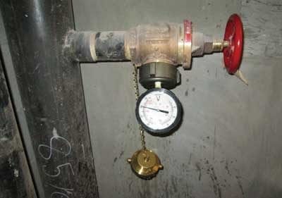
Pressure-reducing valve tests
NFPA defines 5-year and annual testing requirements for all pressure-reducing and relief valves while repeating the requirements for testing these devices that are specifically located at hose connections (Class I and Class III systems) and hose rack assemblies (present in all Class II systems and some Class III systems).
From the 2017 Edition of NFPA 25
13.5 Pressure-Reducing Valves and Relief Valves/13.5.2 Hose Connection Pressure-Regulating Devices/13.5.3 Hose Rack Assembly Pressure-Regulating Devices
13.5.1.2/13.5.2.2*/13.5.3.2 A full flow test shall be conducted on each valve at 5-year intervals and shall be compared to previous test results.
13.5.1.2.1/13.5.2.2.1/13.5.2.2.1 Adjustments shall be made in accordance with the manufacturer’s instructions.
13.5.1.3/13.5.2.3/13.5.3.3 A partial flow test adequate to move the valve from its seat shall be conducted annually.
Each 5-year, full flow test is conducted by taking pressure readings both upstream and downstream of each valve while the highest flow of water expected to run through the valve is running through it (250 gpm for Class I and Class III systems, 100 gpm for Class II). The downstream and upstream measurements are then compared to previous results to ensure that the pressure-reducing valve is dropping the pressure as intended – not too little and not too much.
The annual partial flow test is simple: the hose valve must be opened slightly, just enough to exercise the valve. After doing this, drain any remaining water, close the valve, and reattach the cap – the test is complete.
Master pressure-regulating devices have similar but more frequent testing requirements:
From the 2017 Edition of NFPA 25
13.5.4.2* A partial flow test adequate to move the valve from its seat shall be conducted quarterly.
13.5.4.3 A full flow test shall be conducted on each valve annually and shall be compared to previous test results.
13.5.4.4 When valve adjustments are necessary, they shall be made in accordance with the manufacturer’s instructions.
Note that each pressure-reducing valve in the master assembly must be isolated and tested individually.
Backflow preventer testing
Backflow preventers that prevent stagnant water from reentering the city water supply must be flow tested every year. The “testing” more closely resembles maintenance; it serves to exercise the check valves within a backflow preventer to ensure they don’t get stuck in the closed position. To conduct the test, simply open a connection downstream of the backflow preventer to create system demand flow through the device.
There are two exceptions to this annual testing requirement: If a fire pump test has already been conducted that meets the test requirements, the backflow preventer does not have to be tested separately; and if the system is in an area suffering long-term drought conditions, the test can be skipped, as it uses a lot of water. In the latter case, an inspection of the backflow preventer’s internal check valves will suffice.
From the 2017 Edition of NFPA 25
13.7.2.1* All backflow preventers installed in fire protection system piping shall be exercised annually by conducting a forward flow test at a minimum flow rate of the system demand.
13.7.2.1.1 Where water rationing is enforced during shortages lasting more than 1 year, an internal inspection of the backflow preventer to ensure the check valves will fully open shall be permitted in lieu of conducting the annual forward flow test.
13.7.2.1.2 The forward flow test shall not be required where annual fire pump testing causes the system flow rate to flow through the backflow preventer device.
13.7.2.2 Where hydrants or inside hose stations are located downstream of the backflow preventer, the forward flow test shall include hose stream demand.
13.7.2.3 Where connections do not permit verification of the forward flow test at the minimum flow rate of system demand, tests shall be conducted at the maximum flow rate possible.
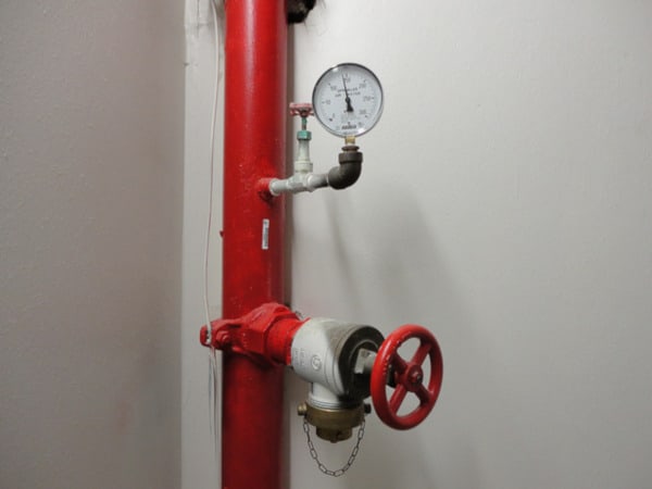
Hydrostatic testing
NFPA 25 technically requires 5-year hydrostatic testing of the “piping from the fire department connection to the fire department check valve” in all standpipe systems, while issuing specific requirements for hydrostatic testing of certain types of standpipe systems. Specifically, all the piping in semiautomatic dry and manual wet and dry standpipe systems must be tested every five years. The exception to this testing requirement is any manual wet system that is combined with a sprinkler system.
That said, the mandate to test portions of all standpipe systems is open to some debate. To read more about this qualification, check out this in-depth look at hydrostatic testing fire safety systems.
From the 2017 Edition of NFPA 25
6.3.2.1* Hydrostatic tests of not less than 200 psi (13.8 bar) pressure for 2 hours, or at 50 psi (3.4 bar) in excess of the maximum pressure, where maximum pressure is in excess of 150 psi (10.3 bar), shall be conducted every 5 years on manual standpipe systems and semiautomatic dry standpipe systems, including piping in the fire department connection.
6.3.2.1.1 Manual wet standpipes that are part of a combined sprinkler/standpipe system shall not be required to be tested in accordance with 6.3.2.1.
6.3.2.2 The hydrostatic test pressure shall be measured at the low elevation point of the individual system or zone being tested.
6.3.2.2.1 The inside standpipe piping shall show no leakage.
13.8.5 The piping from the fire department connection to the fire department check valve shall be hydrostatically tested at 150 psi (10 bar) for 2 hours at least once every 5 years.
Notice the difference in pressure requirements for testing the piping from the fire department connection to the fire department check valve (150 psi for 2 hours) and the testing required for entire systems (200 psi for 2 hours or 50 psi (3.4 bar) in excess of the maximum pressure where maximum pressure is in excess of 150 psi). The purpose of the test is to identify any leaks or other system failures under pressure so that they can be fixed before an emergency. The test is run by applying pressure from a pump at the lowest point in the system for two hours. During this period, a technician must visually expect the piping for leaks while monitoring the pressure gauge for any drop in pressure. NFPA 25 is not specific about what constitutes an acceptable loss of pressure. NFPA 13 allows for up to 5 psi of pressure loss when doing a hydrostatic acceptance test of underground pipe, but underground pipes naturally have a greater amount of leakage. Thus, a code-literal interpretation of results from 5-year hydrostatic testing of existing systems is that any noticeable drop in pressure requires further investigation.
To be continued: The Complete Guide to Standpipe Systems
This concludes part five of our review of standpipe systems; a look at the maintenance testing required for existing systems. In the next installment of this series, we review the regular NFPA testing requirements that only apply to automatic and semiautomatic dry standpipe systems.
If you’re looking to buy components for your standpipe system, QRFS offers a range of gauges, pin racks, fire hose reels, butterfly valves, check valves, and hose angle valves. If you’re searching for a test pump to conduct a hydrostatic test, or a flow or flush test on a manual system, we have those as well.
If you have any other questions about standpipes or need help finding an item, add a comment below, give us a call at 888.361.6662, or fill out our contact form and we’d be happy to assist.
Check us out on Facebook and Twitter!
View Other Posts in this Series on Standpipe Systems:
Part 1: Fire Protection Standpipe System Overview and Introduction to NFPA 14
Part 2: Standpipe System Components and How to Maintain Them
Part 3: More Standpipe System Components and How to Maintain Them
Part 4: Acceptance Testing and Ongoing System Maintenance
Part 5: Maintenance Testing of Standpipes (Continued)
Part 6: Maintenance Testing for Automatic and Semiautomatic Dry Standpipes
Part 7: Standpipe Signs and Markings
Additional Sources:
- NFPA 25: Standard for the Inspection, Testing, and Maintenance of Water-Based Fire Protection Systems (2017)
- Isman, Kenneth E. Standpipe Systems for Fire Protection. Springer International Publishing.
- Gustin, Bill. Testing Pressure-Reducing Valves. Fire Engineering. https://www.fireengineering.com/articles/print/volume-167/issue-1/features/testing-pressure-reducing-valves.html
- Cota, Esteban and Gagliano, Sonja. “Unlocking the Code – Joint Commission Requirements and Understanding NFPA Codes.” Siemens.com.
- https://w3.usa.siemens.com/buildingtechnologies/us/en/events/industry-articles/articles/pages/fss-unlocking-the-code.aspx



Hi – My condo has been served a violation notice and needs a professional to test and submit a report both the sprinkler system and the standpipe system. I live in Jersey City, are there any licensed professionals that can help me with this? Thank you.
Jenny, thanks for commenting. You need to find a licensed fire sprinkler contractor to assist you with testing your fire sprinkler system. We have an article with helpful tips and considerations for when you are selecting a fire sprinkler contractor. Hope this helps!
How does improper installation of water shut off valve and repair of hot water distribution pipe effect the operation of our fire sprinkler system
D — Unfortunately, we don’t have enough specifics about “improper installation” for us to speculate on an answer. Your best bet is to contact a local fire sprinkler pro and ask them to assess the situation.