Learn where seismic cable sway bracing is needed and how to install it
In the previous installment of our series on seismic protections for fire sprinklers, we introduced the principles of sway bracing. Here, we take a detailed look at what goes into designing and installing seismic braces for a fire sprinkler system, specifically focusing on cable sway braces.
Cable braces, because they have no rigidity, require two lengths of cable to do the job of one rigid member. However, they have a huge benefit: they aren’t limited in length like rigid braces—you can run the cable as far as you need to and place it in various positions.
The National Fire Protection Association (NFPA) provides comprehensive guidelines for implementing seismic protections in NFPA 13: Standard for the Installation of Fire Sprinkler Systems (2019 edition).
This article will cover:
- Understanding seismic loads
- Distributing seismic loads
- Noting maximum allowable loads
- Placing sway braces
Installing cable sway braces
Installing cable sway braces
Installing cable sway bracing is relatively uncomplicated, following these two general steps:
- Secure the cable to the structural member with measures such as…
- Looping the cable around the member and swaging it in place with an oval sleeve.
- Looping the cable through an approved anchor and swaging it in place.
- Running the cable to the sprinkler pipe, wrapping it around the pipe twice to form a simple knot, and swaging it in place.
This video from Loos and Co. outlines the options:
Manufacturer guidelines will specify details like the distance of the sleeve from the anchor or pipe, and the angle of the loop. NFPA 13 also has general requirements, including:
- Sway braces should be tight (5.11.2)
- Sway brace components should be arranged in a straight line to avoid “eccentric loading on fittings and fasteners” (5.11.5)
The engineering behind proper sway brace design
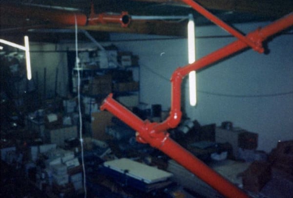
Installing cable sway braces is actually the easy part; figuring out where they should go is more difficult. When sprinkler systems are braced inadequately or not at all, they may fail. In an analysis of fire sprinkler damage from the 1994 Northridge CA earthquake, the World Conference on Earthquake Engineering found that one of the most common conditions associated with sprinkler leakage was a lack of longitudinal bracing.
To properly install cable sway braces in your fire sprinkler system, you need to understand the following:
- Seismic load and how it’s calculated
- The way the seismic load is distributed through zones of influence (ZOI)
- The maximum allowable loads of hardware in the system
- Where sway braces must be placed
What follows is a guide to these concepts and considerations; it is not meant to be comprehensive instructions for designing and installing sway braces. For that, consult a qualified engineer. This post may be particularly useful for fire protection professionals and building managers who are unsure about whether they need or have sufficient seismic protections to meet current standards.
Understanding seismic loads
Remember, seismic braces resist horizontal forces. In an earthquake, the ground and buildings move back and forth and fire sprinkler pipes, including risers and main feed lines, can shake violently. The shaking stresses hanger assemblies and the pipes themselves, possibly to the point of rupture. It can also cause pipes to collide with other objects.
Seismic braces guard against this by tightly securing pipe to structural members, protecting against lateral (perpendicular to the run of the pipe) and longitudinal (parallel to the run of the pipe) shaking.
The fundamental job of seismic braces is to resist the seismic load a system will experience during an earthquake. To properly design and install them, you need to calculate this value for your fire sprinkler system.
Seismic load is a measure of force—the force of a fire sprinkler system shaking back and forth during an earthquake. Calculating the seismic load of a fire sprinkler system is only slightly more complicated than high school physics. Remember F=ma? Force equals mass times acceleration. In other words, bigger and faster-moving objects exert more force.
The specific variation of this formula for calculating seismic loads is found in section 18.5.9.3 of NFPA 13:
Fpw = CpWp
Where …
- Wp is the weight of the water-filled pipes multiplied by 1.15,
- Cp is the seismic coefficient, and
- Fpw is the horizontal force
Note that your authority having jurisdiction (AHJ) may set other requirements for this calculation (NFPA 13: 18.5.9.1).
Calculating weight for seismic loads
The mass portion of this calculation— Wp—is easy to understand. It is the adjusted weight of the water-filled pipe. You should be able to find this information on the manufacturer datasheet for your fire sprinkler pipe. The weight will usually be given in pounds per foot (or kilograms per meter).
If this information isn’t available from the manufacturer, it is likely available online in a chart. For instance, this chart lists known weights per foot for a wide range of sizes of Schedule 40 and Schedule 80 steel pipe. Similarly, this chart lists weights per foot for CPVC pipe.
Don’t forget to include the weight of branch lines in your calculations. You’ll see in our discussion of “zones of influence,” however, that branch lines can sometimes be omitted from these figures.
When calculating the water-filled weight of pipe, NFPA 13 requires a slight correction to account for the weight of miscellaneous hardware attached to the pipe—sprinkler heads, valves, etc. To make the correction, simply multiply the water-filled weight by 1.15 (18.5.9.2). Again, the final value is represented as Wp.
An example of calculating seismic load weight:
Let’s calculate Wp for a 60-foot run of 3-inch nominal Schedule 40 steel pipe with 100 feet of 1-inch nominal Schedule 40 steel branch lines. For each size pipe, we’ll multiply the weight per foot of the water-filled pipe by the length used. The sum of these values times 1.15 is Wp.
Wp = 1.15 x [(length of 3” pipe x lb/ft of 3” pipe) + [(length of 1” pipe x lb/ft of 1” pipe)]
Wp = 1.15 x [(60 ft x 10.8 lb/ft) + [(100 ft x 2.1 lb/ft)]
Wp = 1.15 x [648 lbs. + 210 lbs.]
Wp = 986.7 lbs.
Calculating acceleration for seismic loads
Quantifying the potential acceleration caused by an earthquake is difficult but, thankfully, you don’t have to wrap your head around this problem to calculate the seismic load. NFPA 13 lists values for Cp, the seismic coefficient, which are used to model ground acceleration for seismic load calculations. One Cp value applies for your whole building—and the bigger Cp, the more severe an earthquake that you have to prepare for.
NFPA 13 requires that a value called short-period response parameter, or Ss, be used to determine Cp. Put as simply as possible, Ss represents the acceleration felt by a building during the peak ground acceleration of an earthquake. Don’t worry, you don’t have to calculate this value either.
The US Geologic Survey (USGS) publishes Ss in seismic hazard maps. Additionally, Ss should be available in your building’s engineering plans or from your authority having jurisdiction (AHJ), often your local government’s building department.
To determine Cp, simply find your location’s Ss value in Table 18.5.9.3 of NFPA 13.
If you can’t find your exact Ss value, rounding up only makes you safer. You are also permitted to extrapolate intermediate values of Cp using a linear equation. See the NFPA 13 Annex (A.18.5.9.3) for instructions. If somehow you have no way to determine Ss for your building (which only seems likely in areas that don’t require seismic protections), NFPA 13 permits you to use Cp = 0.5 (18.5.9.5).
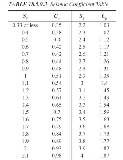
For example, if your building’s plans specify Ss=1.8, then the Cp for your building is 0.84.
Calculating seismic load
Once you know Wp and Cp, determining seismic load is easy. It’s basically F=ma. But again, the exact equation is:
Fpw = CpWp
Where …
- Wp is the weight of the water-filled pipes multiplied by 1.15
- Cp is the seismic coefficient
- Fpw is the horizontal force
Let’s calculate the seismic load using the two previous examples we’ve done—a run of pipe with Wp=986.7 and Cp=0.84. The seismic load is:
Fpw = CpWp
Fpw = 0.84 X 986.7 lbs.
Fpw = 828.828 lbs.
When planning seismic protection for your fire sprinkler systems, you need to keep records of your calculations; section 18.5.11.9.1 notes that your AHJ may require you to submit calculations. NFPA 13 also requires bracing calculations and “zone of influence” information (more on the latter below) to be shown in any fire sprinkler system drawings (27.1.3).
As you can see, calculating seismic load isn’t too complicated. However, you can’t put the load calculated for a whole sprinkler system onto one brace. The seismic load is distributed among several braces, each of which must be able to handle the seismic load of the pipe within its specific zone of influence.
Distributing seismic loads – zones of influence
To design seismic a seismic bracing system, we have to consider the zone of influence (ZOI) for each brace we install. A brace’s zone of influence is all of the pipe for which it is responsible during an earthquake.
But what is the zone of influence for a seismic sway brace? NFPA 13 does not define the term outside of what we have already covered. But the Annex does offer an additional comment:
A.18.5.9.6 The zones of influence do not have to be symmetrical based on brace spacing. It is the intent of NFPA 13 that the chosen zone of influence is the worst-case load scenario.
That said, NFPA 13 does not forbid making the ZOI symmetrical based on brace spacing. As Consulting-Specifying Engineer Magazine explains, in practice, a brace’s ZOI is often assumed to extend halfway to the next brace.
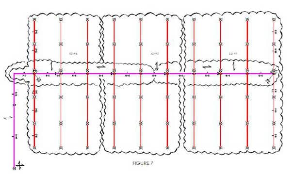
Remember how we included the weight of the branch lines in our seismic load calculation? We did this because, with few exceptions, a brace’s zone of influence includes all branch lines and other pipe connected to the braced pipe.
From the 2019 edition of NFPA 13
18.5.9.6 The zone of influence for lateral braces shall include all branch lines, drops, sprigs, and mains tributary to the brace, except branch lines that are provided with longitudinal bracing or as prohibited by 18.5.9.6.1.
As mentioned, the use of longitudinal bracing on branch lines allows them to be excluded from the ZOI of their main’s brace. After all, such bracing is in the same direction or dimension as the main’s bracing. Designing the main’s lateral brace to prevent the longitudinal movement of already-braced branch lines would be redundant.
There is a case when you may be required to provide longitudinal bracing for branch lines: where riser nipples are present. Riser nipples transfer the seismic load of the branch lines to the mains. During an earthquake, these nipples experience strain. The conditions in which you may skip the longitudinal bracing of branch lines with riser nipples are outlined in section 18.5.9.6.1.
And the zone of influence for longitudinal braces does not include branch lines (18.5.9.7).
Noting maximum allowable loads
Now that you understand the basics of seismic load and ZOI, you can evaluate how different seismic loads stack up against the strength of your bracing hardware. Every component of a sway brace for fire sprinkler systems, including the brace, anchors, fittings, pipe, and structure, have maximum allowable loads. This is the maximum amount of force that any part of the brace can handle.
If the seismic load exceeds the maximum allowable load for the brace, the brace is not suitable and could fail during an earthquake. Knowing what you do about ZOI, it should be apparent that one brace failure will cause the load to be distributed onto other braces, possibly causing a cascade of brace failures and ultimately the failure of the fire sprinkler system.
And the weakest part of a brace determines the maximum allowable load.
Maximum allowable load for bracing cable
Knowing the maximum allowable load of the cable sway braces you want to use is critical. When you go to your vendor to buy these materials, you need to have an idea of the load they will be able to handle.
Using standardized rigid steel materials for braces instead of using cables, as permitted by section 18.5.2.2 of NFPA 13, does have certain pluses: you’ll always be able to find rigid braces that are strong enough for a given load, and pipe only needs one brace. However, standardized rigid steel materials have length limitations. If these materials are too short, they won’t fit in certain set-ups. If they are too long, they would lose their ability to resist buckling.
When you use bracing cable, you aren’t bound by these length considerations. As long as you install it properly, you can (in theory) use as much cable as you need to between the pipes and the structural anchor. The max load that bracing cable can handle depends on the brace angle; the closer the brace is to vertical, the smaller the allowable load. Bracing cable is only permitted (18.5.4.2) when it’s listed for maximum loads, so the maximum allowable load for any bracing cable should be readily available from the vendor or manufacturer.
Again, these are designed to handle horizontal forces; vertical reaction forces only need to be considered in specific conditions outlined in section 18.5.10 (which involve high loads and near-vertical bracing angles). Cable braces are not suitable for purely vertical loads, but there may be a need for bracing against vertical forces that are produced by a horizontal load under those conditions.
Also note that even though a cable brace requires two lengths of cable, each length must support the full seismic load.
Refer to our article on designing seismic bracing systems for more information on different kinds of sway bracing and the relationship between maximum allowable load and angle of installation.
Seismic anchoring requirements
“The weakest link breaks the chain” certainly applies to sway brace design. You can get all the math right for the brace material—use proper strength cable at the proper angle, and put braces in all the right places—but still have your braces fail if the nuts and bolts aren’t up to the task.
When working with bracing cable, you typically use two pieces of hardware to fix the cable to the structure: anchors and fasteners. Fasteners connect the anchors to the structures. Anchors connect to the cable.
NFPA 13 provides extensive information on the allowable loads of different kinds of fasteners applied in different media in section 18.5.12.7 and Tables 18.5.12.2(a-m). These tables let you determine the maximum allowable load for a fastener based on the structural media in question (different types of concrete, and some steel and wood), the type of fastener (including different sizes), the size of the slab, and the distance from the edge of the slab at which fasteners are installed.
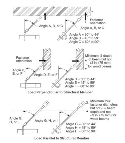
Depending on the geometry of the anchor and the angle of installation, the tension in the brace generates prying forces on the fastener which can cause the fastener to fail. Manufacturers are required to publish pry factors for anchors at different angles of installation (18.5.12.7.2.A). The angle of installation and the pry factor of the anchor are needed to use Tables 18.5.12.2(a-m). The higher the pry factor, the lower the maximum allowable load. That’s why anchors designed to apply low pry to the fastener are so useful.
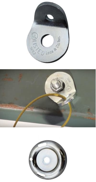
Note that the concrete anchors whose maximum allowable load data is laid out in Tables 18.5.12.2(a-j) are meant to be cast-in—that is, the concrete forms are poured around these anchors. These fittings must be “prequalified for seismic applications” (18.5.12.7.5) and post-installed concrete anchors also must be prequalified for the purpose (18.5.12.7.1). Unfinished steel bolts for post-installation into steel or wood (whose max loads are listed in Tables 18.5.12.2(k-m)) do not have to be prequalified.
The alternative to all of this, as we saw previously in the video from Loos and Co., is to wrap the cable around a structural member—no anchors or fasteners needed.
Fire sprinkler pipe also needs to handle the strain
Fire sprinkler pipe must also meet certain maximum allowable loads when it is braced against earthquakes. The resistance to lateral sway provided by lateral braces is applied in a gradient to the pipe. Thus, the pipe can move very little where the brace attaches to it.
But because of the inherent flexibility of the pipe, points further away from braces have more “play.” If braces are installed too far apart, the pipe can flex and collide with other objects or fail from stress during an earthquake.
To prevent this, NFPA 13 forbids spacing lateral braces more than 40 ft. (12 m) apart on-center (18.5.5.2.2). Beyond this, the seismic load in any ZOI must not exceed the maximum allowable load of the pipe in that ZOI (18.5.5.2.3). The maximum allowable load of the pipe varies based on the type and size of the pipe and the distance between the braces. Tables 18.5.5.2(a-l) list these values for common types of fire sprinkler pipe. As before, we have to consider the weakest link:
From the 2019 edition of NFPA 13
18.5.5.2.4 When determining permissible loads in accordance with 18.5.5.2 or 18.5.5.2.1 on a main with varying sizes, the allowable loads shall be based on the smallest pipe size within the zone of influence.
Make sure the structural elements are sturdy
Finally, any structural member that you attach braces to must be able to withstand the seismic loads applied to it. There are no tables to help you calculate this, though. You need an engineer to point out the right structural elements.
(Tentatively) placing sway braces
Once you understand seismic loads, zones of influence, and maximum allowable loads, the hardest part is behind you. Determining where the braces will go is straightforward.
First, make a tentative plan of where they will go based on NFPA 13’s minimum requirements, which we’ll list below. Then, check that maximum allowable loads are not exceeded and make adjustments as needed. NFPA 13 gives requirements for the placement of lateral braces and longitudinal braces on main lines, for the bracing of changes of direction of main lines, for the bracing of risers, and for the bracing of seismic separation assemblies (see our article on flexible design for more information on these elements).
Lateral seismic braces
Lateral sway braces shall be placed, at minimum, according to the following NFPA 13 requirements:
- No brace shall be more than 40 ft. (12 m) apart on-center from adjacent braces
- If flexible couplings are used in excess of the requirements of Section 18.2, a lateral brace shall be placed no more than 24 in. (600 mm) away from every other flexible coupling (2.3, 18.5.5.9)
- The last brace shall be no further than 6 ft. (1.8 m) on-center from the end of the pipe (5.5.5)
Longitudinal seismic braces
Compared to lateral braces, fewer longitudinal sway braces are needed on pipe mains. They are required according to the following rules:
- Feed and cross mains shall have longitudinal braces no more than 80 ft. (24 m) apart on-center (5.6.1)
- A longitudinal brace shall be placed no more than 40 ft. (12 m) from the end of the main pipe or a change in direction of the pipe (5.6.3)
NFPA 13 seismic bracing requirements for risers
When NFPA 13 discusses the bracing of risers, it generally does not refer to small vertical pipe such as sprigs or drops to sprinkler heads (except as discussed previously with riser nipples). Instead, it refers to the system risers that distribute water vertically through different floors to cross mains.
Because risers are typically vertical, there is no distinction between lateral and longitudinal bracing. As such, risers are provided with 4-way braces. For cable bracing, this means 4 lengths of cable bracing the riser in 4 directions, 90 degrees apart.
Risers need 4-way braces according to the following rules:
- They shall be braced within 3 ft. (900 mm) of the top of the riser (5.8.1) unless the riser is less than 7 ft. (2.1 m) tall and terminates above the roof or top landing (18.5.8.1.1)
- There shall be no more than 25 ft. (7.6 m) between each four-way brace on a riser (5.8.4)
Bracing and changes of fire sprinkler pipe direction
Changes in the direction of horizontal pipe don’t require the same degree of bracing as the ends of pipes because they aren’t cantilevered—but they also may need extra protection. Pipe runs greater than 12 ft. (3.7 m) in length must have their own lateral and longitudinal sway bracing (18.5.7.2). Beyond this, remember that when the pipe changes direction, the cumulative distance through the turn of the pipe is what is measured for all calculations of load on pipes (18.5.5.6).
Whether for changes in direction of main lines or smaller lines branching off, lateral braces are sometimes permitted to act as longitudinal braces for adjacent lines. The reverse is also true. Here are the requirements:
From the 2019 edition of NFPA 13
18.5.6.2 Longitudinal braces shall be allowed to act as lateral braces if they are within 24 in. (600 mm) of the centerline of the piping braced laterally.
18.5.5.8 Lateral braces shall be allowed to act as longitudinal braces if they are within 24 in. (600 mm) of the centerline of the piping braced longitudinally and the lateral brace is on a pipe of equal or greater size than the pipe being braced longitudinally.
Braces can also do double-duty at the junctions of risers and main lines. A 4-way brace for a riser may be attached to a horizontal pipe as long as it is placed with 24 in. (600 mm) of the riser, on-center (18.5.8.3). Conversely, 4-way braces on risers can also provide lateral and longitudinal bracing for horizontal pipe (A.18.5.8.1).
Remember, any time that a brace does double duty, its ZOI is larger and it has to be able to bear the added seismic loads.
Branch line restraint
Branch lines, except as we discussed previously, do not require bracing. They do, however, require “restraint” to keep them from moving too much during an earthquake. Restraint of branch lines can be done in several ways (18.6.1), including with wrap-around u-hooks, No. 12 440 lb. (200 kg) wire, and certain pipe hangers.
You can also use listed sway brace assemblies. Branch line restraints must be attached to the end of the line according to the instructions in 18.6.3.1 and additionally spaced along the branch line according to 18.6.4, based on the size of the pipe and the Cp value.
Putting it all together—designing sway braces for your fire sprinklers
With an understanding of seismic loads, zones of influence, the maximum allowable loads of different hardware, and the required placement, you can design and install sway braces for your sprinkler system. Follow these steps:
- In your design plans, tentatively place sway braces and restraints according to the minimum requirements from NFPA 13.
- Then, determine the seismic load on each brace. Compare this value to the maximum allowable loads for each brace assembly.
- If seismic loads exceed the maximum allowable loads, revise your plans to include more braces.
- If seismic loads are within the maximum allowable loads for your braces, finalize your plans and install the braces.
This blog was originally posted at blog.qrfs.com.


