Fire sprinkler design takes expertise and meticulous planning
Fire sprinkler systems save lives. When a fire breaks out, standard spray sprinklers control the blaze by cooling and wetting surfaces to deprive it of fuel sources and prevent flashover, the sudden ignition of everything in a room when it reaches autoignition temperature. Some sprinkler types in specific systems take this further—they’re designed to completely suppress a fire in more challenging environments like storage facilities.
But how are fire sprinkler systems designed, from fire sprinkler head types to pipe to pressure? It’s a pretty complicated process, so we obviously can’t explain everything. But this article gives an overview of the basic steps of fire sprinkler system design, including:
- Identifying and evaluating the water supply
- Determining what kind of sprinkler system the building needs
- Identifying the hazard level of the building and the protection required
- Picking and laying out sprinkler heads
- Choosing and laying out pipe
At each step, we explain broadly what a designer has to do, including the calculations (financial and technical) involved. We’ll frequently refer to NFPA 13: Standard for the Installation of Sprinkler Systems (2019 edition), the document adopted by jurisdictions that govern commercial fire sprinkler system design.
Fire sprinkler design is a detailed process, and designers are highly skilled and qualified professionals. They frequently hold a Professional Engineer (PE) certification and meet local and state licensing standards. Jurisdictions often defer testing and licensing for sprinkler system layout to the National Institute for Certification in Engineering Technologies (NICET). Usually, at least a NICET Level III Water-Based System Layout certification is required to work without supervision as a sprinkler system designer.
Start with the basics—determining the water supply
Sprinkler system design begins with water— everything else depends on having enough of it ready to control a fire. NFPA 13 requires an automatic water supply for sprinkler systems (5.1.2), meaning that the water will flow through sprinkler heads without any human intervention.
Many possible sources can be used, including city water, ponds, rivers, reservoirs, water tanks, pressure tanks, and gravity tanks or water towers. But in most cases, a municipal waterworks is the go-to supply.
Whatever the source, it must have sufficient capacity for fire control (5.1.3). The factors that determine capacity include flow rate (in gallons per minute, GPM), pressure (in pounds per square inch, PSI), and duration (how long it can maintain the required pressure and flow). For a municipal water supply, capacity is determined with a flow test performed at nearby fire hydrants.
A flow test requires at least two hydrants, A and B. First, a static pressure reading is taken at hydrant A while neither hydrant is flowing water. Then, hydrant B is opened wide and another pressure reading is taken at hydrant A. This residual pressure reading is the amount of pressure that can push water through sprinkler heads (minus some losses). A pitot tool is used to measure the pressure of the water flowing from hydrant B. In this video, Grapevine, TX’s fire department shows how to conduct a flow test:
This value is used to calculated flow as follows:
Q=29.83 x C x d2 x
With:
Q = flow rate (GPM)
C = C-factor, the roughness coefficient of the hydrant outlet
d = inside diameter of the outlet
P = pressure observed at hydrant B
The water supply capacity is the foundation of sprinkler system design. Many of the steps following this one are all about ensuring hydraulic demands won’t exceed this capacity. Designers choose pipes and sprinklers to make the hydraulic calculations work out. If they can’t do it with the available flow and pressure, they have to resort to using a fire pump (which may cost tens of thousands of dollars) to boost the water supply.
Check out our blog for more information about tools and kits used for flow tests. If you are conducting flow tests, shop for test kits, pitot gauges, and hydrant wrenches.
Know the building—what kind of sprinkler system does it need?
If the first step of sprinkler system design is knowing the water supply, the second is understanding the building. Sprinkler system designers sit down with the architectural and engineering plans to sort out just what the building needs from a sprinkler system. Is it a residential structure? Industrial? How significant is the fuel load? Will it have climate control?
Questions like these. determine the requirements the system should meet and what kind of sprinkler system is appropriate.
NFPA 13, NFPA 13R, or NFPA 13D—which standard to use?
As mentioned, NFPA 13 is the go-to standard for commercial sprinkler system design. NFPA 13-compliant systems are defined by full sprinkler coverage. The standard is typically used in commercial facilities—offices, mercantile spaces, warehouses, industrial buildings, etc.
Two alternatives to NFPA 13 exist:
- NFPA 13R: Standard for the Installation of Sprinkler Systems in Low-Rise Residential Occupancies
- NFPA 13D: Standard for the Installation of Sprinkler Systems in One- and Two-Family Dwellings and Manufactured Homes.
NFPA 13R and NFPA 13D both focus on affordable and convenient life safety protection, so they don’t require sprinklers in unoccupied spaces like closets and attics. But in some larger residential settings, a full-coverage NFPA 13 system is still used.
Does the building need a wet, dry, or preaction system?
In addition to determining the standard, designers also have to figure out whether a building needs a wet pipe system, dry pipe system, or preaction sprinkler system.
Most buildings simply use a wet sprinkler system in which water fills the pipes at all times. As soon as a sprinkler head operates, water flows.
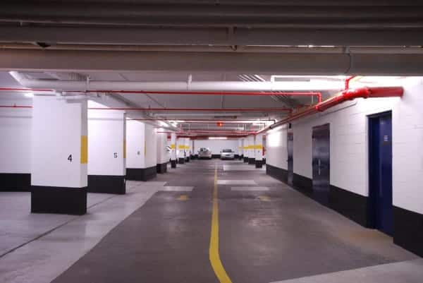
Structures like parking garages where freezing is a concern need dry pipe systems, so named for the absence of water in the pipes. A dry valve, held shut by a pressurized gas, stops the water in an insulated section of the pipe until its needed. When a sprinkler head activates, the gas depressurizes, the dry valve opens, and water flows.
Where the cost of an accidental discharge would be severe (such as in an art gallery), a preaction system may be used. Water is held back by a preaction valve, which may also function as a dry valve. Activation also relies on a separate trigger, such as electric input from a smoke or heat detector, providing another layer of control over whether the water flows from sprinklers.
Know the building—how much water is needed for fire sprinkler design, including the hazard level?
How much water does it take to control a fire? This depends on many factors, including the size of the fire and the type of fuel. Three conceptual tools help designers plan systems that can produce sufficient water flow and pressure: occupancy hazard, design area, and density/area curves.
Occupancy hazard
NFPA 13 groups (4.3) buildings or portions of buildings into occupancy hazards, helping designers estimate the fuel load and thus the water demands. The assignment of an occupancy hazard depends on several factors explained in NFPA 13:
19.3.1.2.3 Occupancies or portions of occupancies shall be classified according to the quantity and combustibility of contents, the expected rates of heat release, the total potential for the energy release, the heights of stockpiles, and the presence of flammable and combustible liquids, using the definitions contained in 4.3.2 through 4.3.7.
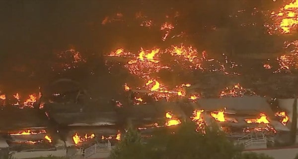
NFPA 13’s hazard classifications are (19.3.1.2.4):
- Light Hazard
- Ordinary Hazard (Group 1)
- Ordinary Hazard (Group 2)
- Extra Hazard (Group 1)
- Extra Hazard (Group 2)
- Special occupancy hazard (including storage)
It’s important to note that NFPA 13’s occupancy hazard categories apply only to the design of sprinkler systems and “shall not be intended to be a general classification of occupancy hazards” (4.3.1.2). NFPA 101: Life Safety Code also groups buildings into occupancy hazards, but these classifications are different; they’re related to threats to life, not fuel load.
Design area
The design area concept lets designers select a worst-case scenario part of their building to base the whole system around. As with hazard level, “worst-case scenario” refers to hydraulics. The design area is a “hydraulically challenging” location, usually because of high elevation and/or its distance from the fire sprinkler riser. The design area concept is used because it would be impractical to supply every fire sprinkler with water at once.
Identifying a design area isn’t always straightforward, so layout professionals often perform calculations for multiple areas to find the one with the highest demand. NFPA 13 has various rules for the selection of the design area.
Density/area curves
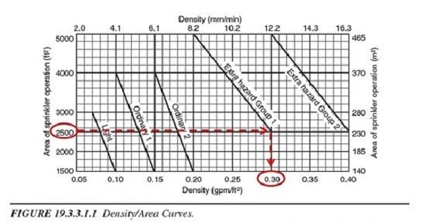
Designers use the hazard level and design area to determine how much water they need with density/area curves. “How much water” means water density—gallons per minute per square foot (GPM/ft2). When designers know the hazard level of their building and the size of the design area, they can use the density-area curves (19.3.3.1.1) provided by NFPA 13 to determine the exact required water density.
Once the design area density is determined from the curve, calculating the total required flow is simple. Flow (GPM) is density times area.
Laying out sprinkler system components—sprinkler heads
Sprinkler system design is an iterative process. Designers have to tentatively plan a set-up and then check the math to see if the hydraulic calculations work out. One part of this process involves laying out and sizing the sprinkler heads.
Laying out sprinkler heads and determining their coverage area in fire sprinkler design
To know how much density a sprinkler can deliver, a designer must first determine the area it covers. They follow guidelines from NFPA 13 to ensure that sprinklers cover an appropriate amount of space.
Tables 10.2.4.2.1(a-d) tell how far apart, on center, standard-spray upright and pendent fire sprinklers can be. The max distance is 15 ft., but this is reduced in many situations. Whatever distance between sprinklers is allowed, the heads can be no more than half that distance (10.2.5.2.1) from the walls. So, the max length from a sprinkler to a wall is 7.5 ft.
Designers mark the location of sprinklers and pipes on the plans based on these rules and then determine how much space each head protects according to NFPA 13’s rules. There is a limit to how much floor space one sprinkler can reasonably cover. These maximum protection areas for standard spray sprinklers are also laid out in Tables 10.2.4.2.1(a-d); the biggest possible value is 225 ft.2, but this is only applicable in noncombustible unobstructed spaces. (And note that different types of sprinklers, such as extended coverage, have different rules and values.)
Protection area, As is calculated with the formula As=S x L (9.5.2.1). Along the branch line, S is the larger of either:
- The distance to the closest sprinkler
- Twice the distance to the closest obstruction or wall
The value of L is determined in the same way but perpendicular to the branch line (e.g., in the direction of the next branch line).
Sprinkler K-factor determines the flow a sprinkler can produce
Sprinkler system designers have a lot of sprinklers to choose from when designing a system. There is an incredible array of temperature ratings, finishes, and performance characteristics available. But when it comes to the hydraulics of sprinkler system design, perhaps the most critical sprinkler spec is K-factor, which is essentially its orifice size.
Every sprinkler has a defined K-factor, which describes how much flow (GPM) it can produce at a given pressure (psi). Common K-factor values include 2.8, 5.6, and 8.0. The relationship between K-factor, flow (q), and pressure (p) is:
K=q/√p
Designers often select a common K-factor and check to see if they can achieve the required flow with the available pressure. If they can’t, they may choose another K-factor. Or, they may change something about the pipes to boost the available pressure.
Laying out system components—pipes, fittings, and hydraulic calculations in fire sprinkler design
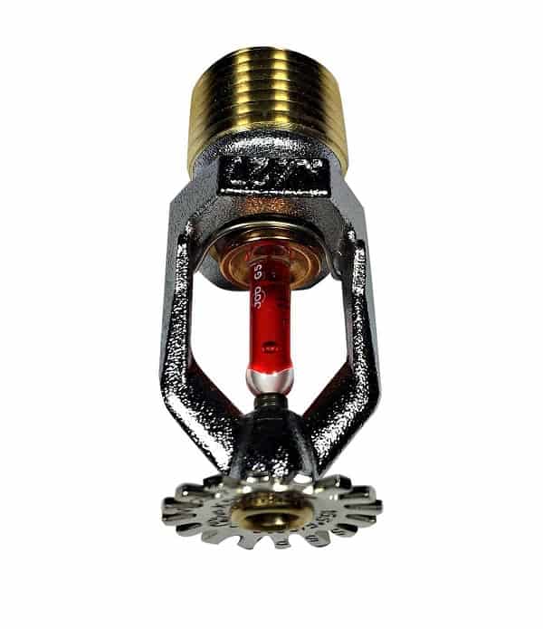
When designers lay out a sprinkler system on paper (or digitally, nowadays), they mark where the pipes will go and decide their size and material. Pipe selection affects hydraulic calculations, cost, corrosion resistance, and more.
The flow test only tells designers how much pressure is available from the source and at the base of the system riser. They have less to work with at the sprinkler heads because of head loss. Head loss is the loss of pressure due to resistance as fluid flows in pipes from its source to its destination.
Three kinds of resistance create head loss—gravity, friction, and turbulence. Designers can’t fight the effects of gravity unless they use pumps; no matter the pipes’ diameter, 0.433 psi is lost for every vertical foot. But they can and do select pipes, fittings, and devices to reduce the head loss from friction and turbulence.
Pipe selection and friction loss
The friction of water against the walls of the pipe fights against the pressure from the water supply. The size of the friction force depends on three factors:
- The rate of flow (q)
- The empirical roughness of the pipes (C; small C means rough pipe)
- The diameter of the pipes (d)
Designers use the Hazen-Williams formula (27.2.2.1.1) to calculate pressure loss per foot of pipe (p):
p = (4.52Q1.85) ÷ (C1.85d4.87)
Selecting appropriate fire sprinkler pipe materials and sizes helps minimize friction losses. If hydraulic calculations reveal that a sprinkler head in the design area won’t get enough pressure to produce the design density, the pipes’ size can be increased to reduce pressure loss.
Pipe material also affects the pressure losses. C-value describes the roughness of the pipe, and pipe made of copper (C=150) or CPVC (C=150), for example, is smoother than one made of unlined cast iron (C=100).
With pipe size and material, there are considerations other than the hydraulic calculations. Up-front and long-term costs are also important things to think about. Bigger pipe costs more, and copper pipe costs more than thermoplastics, for example. Nonmetallic pipes like CPVC also have unique concerns regarding exposure and melting and can only be used in specific settings.
Balancing cost and function is a major part of a fire sprinkler system designer’s job.
Devices and fittings and turbulence loss
Turbulence also creates pressure loss. Devices (such as valves) and fittings (like elbows and tees) create turbulence that, in turn, decreases the amount of pressure available downstream. Turbulence occurs when water is forced to change direction or pass through small orifices.
The math behind turbulence loss is complicated, but NFPA 13 allows designers to estimate head loss from devices and fittings in terms of equivalent feet of pipe (27.2.3.1.1). Tables from either NFPA 13 or manufacturer data indicate what length of pipe will create the same head loss that a particular device or fitting makes.
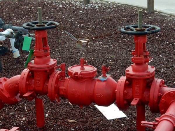
There are pressure-eating devices that can’t be left out of the equation. For instance, backflow preventers are frequently required to prevent the contamination of municipal water supplies. If the city supply loses pressure for whatever reason, stagnant water in a fire sprinkler system could flow backward, contaminating potable water. Backflow preventers tend to create large head losses, but this is unavoidable where they are required.
Fire sprinkler system design takes a pro
Designing fire sprinkler systems involves many elements. Designers check the water supply, identify building needs, lay out pipes and sprinklers, and perform hydraulic calculations. It’s a complicated process, and we’ve barely scratched the surface in this article.
Sprinkler systems definitively save lives and property, but they only work as intended when they’re well-engineered and up to code. Always rely on a licensed professional to design a fire sprinkler system. And note that different states and municipalities may have additional requirements from what’s specified in NFPA 13.
A widely accepted credential is the NICET Level III certification in Water-Based System Layout, which qualifies a designer to work without supervision. If you’re interested in becoming a sprinkler system designer, an excellent place to start is on-the-job training in a design, pipe-fitting, or sprinkler installation firm, along with an engineering degree and eventual certification.
This blog was originally posted at blog.qrfs.com. If this article helped you, check us out at Facebook.com/QuickResponseFireSupply or on Twitter @QuickResponseFS.


Dear Sir,
Please, I need your guide in design calculation for fire sprinkler system on how to calculate for the following:
1). Flow rate calculation
2). Pipe sizing calculation
3). Pressure require calculation
3). Fire pump sizing calculation
I would greatly appreciate if you could kindly help and forward any typical calculation process you have done on any project as a guide.
I shall be expecting your swift response.
Best regards.
Ebenezer — Unfortunately, QRFS does not design fire sprinkler systems; we are equipment providers. In addition, the blog above is designed to be a primer on the considerations involved and how designers approach this task. An individual project has many, many unique considerations that call for the services of a professional system designer. You should contact a design professional in your area and have them scope the project! Best of luck and thanks for reading!
Hi, on K Factor : how does one work out the flow at different pressures? Say 5.6 (80) sprinkler heads on a 7.5 bar pressure maintained ring main?
Also another question if I may. We have a pressurised ring feeding seven sprinkler control valves. Does (and why) fire brigade booster connections have to be above the control valves? It seems to make sense (to me) that the FB boost would have the same effect anywhere on the ring main?
Thank you from literally half a world away!
Johan — For detailed system application questions like this, you can try our Ask a Fire Pro service. Click the link to submit your question with some information about your building or system, and a fire protection professional will provide an answer based on standards and codes. Our pros include AHJs, contractors, engineers, and code experts with 150+ years of combined experience!