

Newer editions of NFPA 13 no longer specify using density/area curves for fire sprinkler system design
All fire sprinkler system designs revolve around water flow. The size and material of pipes, the water supply’s pressure, the placement and size of sprinklers, and nearly every other design decision aim at achieving sufficient water flow to control or suppress a fire. Until recently, a major feature of fire sprinkler hydraulic calculations was the density/area curve. However, this concept was totally removed in the 2025 edition of NFPA 13: Standard for the Installation of Sprinkler Systems—and phased out in prior editions.
The move away from sprinkler density/area curves and their replacement with single-point design criteria ultimately shouldn’t affect existing systems, and it will change little about how designers perform hydraulic calculations. However, it is still a notable shift in approach. This article is your guide to:
- The basic background on NFPA 13 hydraulic calculations and the density/area concept
- How water density calculations worked with density/area curves (and why designers chose different points on the curve)
- Why the NFPA 13 committee removed these curves in favor of point-based design
- The implications for existing fire sprinkler systems that need to be evaluated or modified
QRFS is your fire sprinkler source. We have the commercial and residential fire sprinkler heads you need, plus escutcheons, cover plates, wrenches, pipes and fittings, and much more.
Fire sprinkler hydraulic calculation basics and the density/area concept
To understand the reason behind the removal of density/area curves from NFPA 13, we need to review the density/area concept. While NPFA 13 contains multiple design methods for sprinkler systems—including the room design method, the pipe schedule method, and special parameters for storage systems—density/area is foundational. This concept enables designers to link the “why” of a sprinkler system with the “how.”
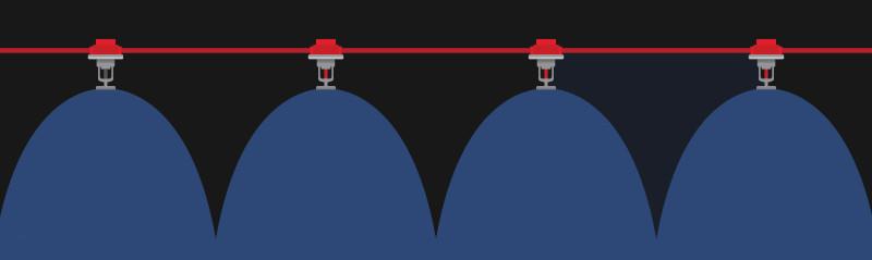
The “why” of sprinkler system design is getting things sufficiently wet. Depending on the design objective, enough sprinklers must spray sufficient water to attack a fire directly to suppress it or wet fuel sources to control its spread. Engineers need numbers—how wet should a design area get? Water discharge density, aka “water density” or “design density,”quantifies this metric in gallons per minute per square foot. As long as sufficient water density blankets a space via properly spaced and supplied sprinklers, the system can achieve its design objective.
If getting things sufficiently wet is the aim of fire sprinkler systems, hydraulic design is the “how.” Designers connect sprinkler systems to suitable water sources, choose sprinklers with proper K-factors (the size of the hole in sprinklers), size pipes appropriately and choose their material, account for a loss of pressure from friction and gravity, and specify fire pumps to augment the pressure and flow as needed.
The density/area concept, along with the K-factor of sprinklers, links the why and how by allowing designers to evaluate the required density and convert it into the water pressure needed to accomplish it. Here’s how that works:
1. Using the specified water density and design area size—both of which come from NFPA 13 rules based on a given occupancy hazard—they can calculate the design flow rate:
Density (gallons/minute/ft2) x Area (ft2) = Design flow (gallons/minute) for the whole design area
2. This flow rate is for the entire sprinkler design area. Designers next calculate the flow rate for a single sprinkler using the sprinkler coverage area. The coverage area can be complicated and depends on the type of sprinkler (e.g., ordinary versus extended coverage) and the placement of individual sprinklers, branch lines on which the sprinklers sit, and walls. However, simply put:
Design area (ft2) ÷ Sprinkler coverage area (ft2) = number of sprinklers (round up to the next whole number)
Design flow (gallons/minute) ÷ number of sprinklers = Per sprinkler flow rate (gallons/minute)
3. The design pressure required at a sprinkler head (which forms the basis for pipe sizing and pump selection) is calculated using the sprinkler K-factor formula. By selecting sprinklers with bigger K-factors, designers can lower the required pressure to achieve a given flow.
Flow (gpm) ÷ K-factor]2 = Pressure (psi)
You can read more about this process in our previous blogs, including “How Much Water Pressure is Required for Fire Sprinkler Systems?” and “The Elements of Fire Sprinkler System Design.” Note that both blogs were written with NFPA 13’s 2019 edition in mind, including the use of density/area curves.
Designers have different tools to achieve the requisite design flow and pressure, such as increasing sprinklers’ K-factors to reduce the necessary pressure, choosing different-sized pipes or pipe materials that cause less friction, or increasing the water supply’s pressure with a pump. However, ultimately, the density and design areasquare footage values, based on occupancy, form the basis of all the other possible decisions.
A review of density/area curves in NFPA 13
Again, the necessary water density and design area values are essential numbers in hydraulic calculations. Before the 2022 edition of NFPA 13, designers got these values from the standard’s density/area curves:
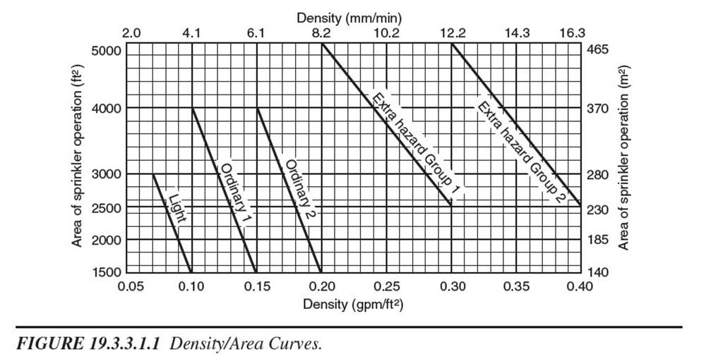
For each occupancy hazard level, the slanted lines plot allowable density values against allowable design area sizes. For example, in the graph above, an Ordinary Hazard Group 1 occupancy with a 4,000 square-foot design area needs to achieve a 0.11 water density (simply follow the very top of the slanted line to the x and y axes to see this example).
For any given occupancy hazard, any point on the line is acceptable:
- The bottom point on the line (smaller area, higher density)
- The top point on the line (bigger area, smaller density)
- Any point in between (calculated with basic algebra; y=mx+b)
The curves afford some flexibility for designers, with different advantages at each end of the spectrum. At the bottom of the curve, the water density and the flow per sprinkler (and thus the required water pressure) are higher, but the total required water flow in the design area is smaller. At the top of the curve, the total water flow demand from the system is higher, but the per-sprinkler flow (and pressure) is lower. We calculated some of these values based on the Ordinary Hazard Group 1 curve below:
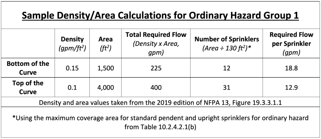
Despite having these options, the bottom point of the curve was typically considered the most economical and most effective solution, for reasons we’ll discuss shortly. This led to many designers exclusively using the lowest point of the curves. It also eventually led the NFPA 13 committee to remove the entire concept of density/area curves from the standard.
Point-based design and the removal of density/area curves in NFPA 13 hydraulic calculations
The process of removing density/area curves from NFPA 13 arguably started all the way back in 2002, when a motion to delete the graphs narrowly failed to make it through the standard development process for that edition. The change finally took shape officially in 2022 and 2025.
The 2022 version of the sprinkler standard provided density/area curves as an option for evaluating existing systems only but required a single-point design for new systems (19.2.3.1.1). The 2022 edition still provided the density/area curves in Figure 19.2.3.1.1, but this figure was removed entirely in the newest edition, the 2025 version of NFPA 13. Under the latest standard, new and existing systems use the single-point approach (or an alternative like the room design method).
In 2022 (new systems) and 2025 (all systems), the density/area method now uses single values taken from Table 19.2.3.1.1. For simplicity’s sake, we’ve reproduced the values from this table for the most common case below, “Where the Design Area is Not Required to be 3000 ft2.” Note: the design area is required to hit the 3,000 square foot threshold, with some exceptions, when protecting buildings that have “unsprinklered combustible concealed spaces (19.2.3.1.5).” Special occupancy hazards also have different design criteria (19.2.3.2.1.1).
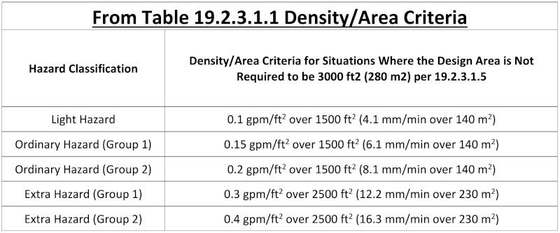
If you look back at the old density/area curves graph found in previous iterations of NFPA 13, you’ll notice that the values in the above table are identical to the bottom points of the curves. As mentioned, the NFPA 13 committee moved to this point because it’s economical and provides superior performance. The standard discusses this fact in the supplementary materials in the 2019, 2022, and 2025 editions of section 19.2.3.1.1. Overall, the smallest design area, while requiring higher pressure, requires less overall water flow and confines the fire to a smaller area.
Additionally, it is still possible to reduce the required water pressure without using the upper portion of the old density/area curve by using large K-factor sprinklers. As the 2025 edition of NFPA 13 explains, the density/area curves were developed in the 1960s and 1970s with only 5.6k and 8.0k sprinklers available. Now that sprinklers with different and larger K-factors are approved and available, it’s possible to achieve higher flow rates without increasing water pressure.
What happens if I need to evaluate or modify an existing system?
Sometimes, when the use, occupancy hazard, water supply, stored commodities, or building structure change, it becomes necessary to evaluate the fire sprinkler hydraulic calculations used for the system to see if changes will be required. Although density/area curves were removed entirely from the 2025 edition of NFPA 13, designers can still evaluate existing systems using the version of NFPA 13 used in their original design and installation—including by using the old design curves.
The 2025 edition says this:
30.4.2 Evaluation.
Evaluation of existing systems shall be in accordance with one of the following methods:
(1) As a new system in accordance with this edition of the standard
(2) In accordance with the edition of NFPA 13 utilized in the design and installation of the system
For systems predating the 2022 updates to NFPA 13, designers have the choice of using the new single-point design criteria or older design curves. The explanatory material from NFPA 13 makes this clear:
Section 30.4 provides guidance that, for the evaluation of existing systems, the edition of NFPA 13 used for the original design and installation, and the density/area curves from that edition, may be utilized.
Even without density/area curves, fire sprinkler hydraulic calculations remain mostly unchanged
Density/area curves were a feature of NFPA 13 for many editions, so their removal is a significant revision. Now, designers must use more “conservative” high-flow and high-pressure design criteria instead of choosing from a range of options. However, this approach is generally recognized as superior in terms of fire control and efficiency anyway, and it was already favored by many designers who won’t notice the change. Ultimately, the fundamentals of fire sprinkler hydraulic calculations within the density/area concept remain the same.
QRFS aims to be your fire sprinkler resource. Our Thoughts on Fire blog covers technical and practical questions about fire sprinkler equipment, codes, and standards. Our online catalog offers commercial and residential fire sprinkler heads, sprinkler escutcheons, cover plates, wrenches, and a wide range of other fire protection supplies.
If you have questions or need help finding a part, contact us at support@qrfs.com or 888-361-6662.
This blog was originally posted at blog.qrfs.com.
