

Butterfly valves provide lightweight and low-cost control over water flow in fire sprinkler and standpipe systems
A butterfly valve isolates or regulates the flow of fluid through piping systems. While they can be used with liquids, gases, and even semi-solids, butterfly valves for fire protection serve as control valves that turn on or shut off the flow of water to the pipes serving fire sprinkler or standpipe systems.
In this article, QRFS explains how they work, their components, and the different types that are available.
If you’d like, you can click here to browse our selection of butterfly valves for fire protection.
How does a butterfly valve work?
A butterfly valve for fire protection starts, stops, or throttles the flow of water via the rotation of an internal disc. When the disc is turned parallel to the flow, water can pass through freely. Rotate the disc 90 degrees, and the movement of water into the system piping stops. This thin disc can stay in the water’s path at all times without significantly slowing the movement of water through the valve.
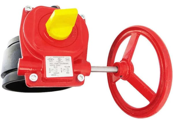
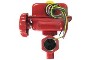
The disc’s rotation is controlled by a handwheel. The handwheel rotates a rod or stem, which turns the disc and simultaneously rotates a position indicator — usually a brightly colored piece sticking out of the valve — that shows the operator which way the disc is facing. This indicator allows for at-a-glance confirmation of whether the valve is opened or closed.
The position indicator plays an important role in keeping fire protection systems operational. Butterfly valves serve as control valves capable of shutting off the water to fire sprinkler or standpipe systems or sections of them. Entire buildings can be left defenseless when a control valve is unintentionally left closed. The position indicator helps fire professionals and facility managers spot a closed valve and re-open it quickly.
The position indicator on this butterfly valve moves in sync with the disc to identify the valve’s “Open” or “Closed” position
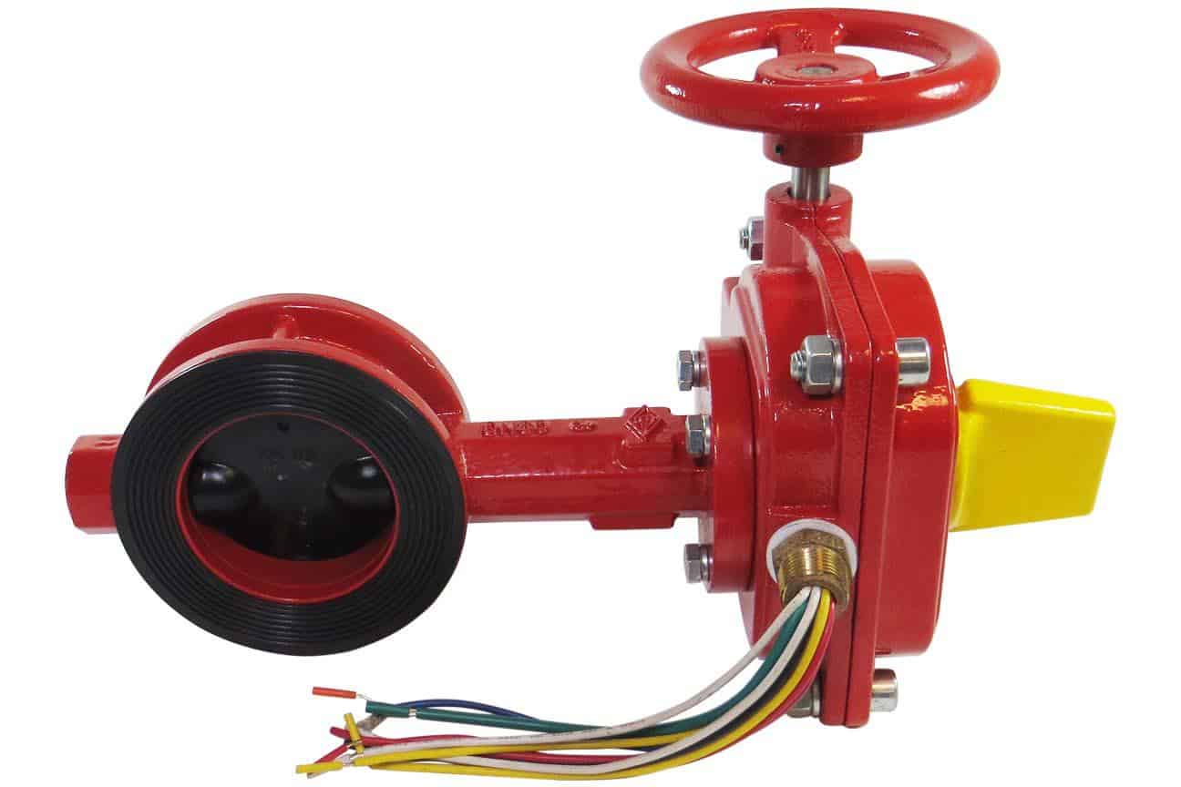
Most butterfly valves for fire protection also include electronic tamper switches that communicate with a control panel and send an alarm when the valve’s disc rotates. Often, they include two tamper switches: one for connection to a fire control panel and another for connecting to an auxiliary device, such as a bell or horn.
What components should I look for?
Butterfly valves consist of only four main components:
- A body, which houses the disc, stem, and seat
- A disc controls the flow of fluid through the valve
- A stem used to rotate the disc and position indicator
- A seat, which forms a water-tight seal with the disc when the valve closes
Their simple design makes them a cost-effective choice compared to other types of control valves. Because they are lighter, more compact, and easier to install than their common predecessor, the OS&Y gate valve (“outside stem and yoke” or “outside screw and yoke”), most fire installers now favor using a butterfly valve as the control valve. Nevertheless, OS&Y valves still have both adherents and their place, which you can learn about here.
The components to consider when selecting a butterfly valve depend on the needs of the installer and the type of pipe used. Although they are made with a variety of valve seats, their seats are almost exclusively EPDM rubber-lined in fire protection. EPDM is favored for its resistance to weather, high and low temperatures, various chemicals, and leakage.
What is a wafer butterfly valve?
The wafer butterfly valve is designed for use with flanged piping systems — it’s held in place using two flanges and a series of nuts and bolts. A wafer valve needs to have the flanges on either side of it connected to each other to hold the valve in place. Consequently, the fire sprinkler or standpipe system must be shut down and drained before installing or removing these valves.
What is a grooved butterfly valve?
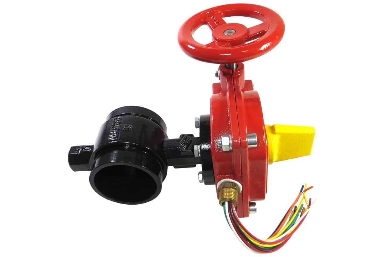
A grooved butterfly valve is a control valve designed for pipes with grooved ends. The valve connects with simple pipe couplings and gaskets that install considerably faster while forming a leak-tight seal. This design makes it easier to replace pipes downstream of the valve. With the valve closed, the coupling downstream from the water supply can be removed while the upstream coupling remains attached, shutting off the water to that section.
These valves are the modern replacement for lug-type valves, which use threaded inserts, or “lugs,” that enable installation by bolts alone. Grooved butterfly valves are available for 2 1/2-inch and larger pipes.
What is a threaded butterfly valve?
A threaded butterfly valve has the same internal components as wafer or grooved versions, but both connections are threaded (it screws onto the pipe). Threaded butterfly valves require precision and accuracy during the installation process because the ends must be threaded on both sides. They are available in multiple sizes, but 1-inch to 1 1/2-inch sizes are the most common.
What are the benefits and drawbacks of a butterfly valve?
In comparison to other valve types, notably OS&Y valves, butterfly valves are relatively lightweight, especially at larger sizes. Because they embody a simple and economical design, they have fewer parts, which makes them easier to repair and maintain. Further, their straightforward design often reduces the time required to install one, decreasing labor costs. However, because butterfly valves leave some of the disc in the water’s path when they are open, they create more friction compared to OS&Y valves, which open the path completely. Thus, some system designers may prefer OS&Y valves in certain scenarios, while other designers account for this friction in the system’s hydraulic calculations.
You can read this blog to learn more about OS&Y valves and how they are different from butterfly valves.
Butterfly valves range in size, pressure ratings, and temperature ratings. In fire protection, they are available for pipes as small as 1 inch and as large as 12 inches in diameter. Many have pressure ratings as high as 300 PSI.
Do they require periodic maintenance?
To comply with the National Fire Protection Association’s NFPA 25: Standard for the Inspection, Testing, and Maintenance of Water-Based Fire Protection Systems, butterfly valves may require weekly inspections (2023 edition: 13.3.2.1). However, if the valve is locked or supervised, that interval extends to monthly (13.3.2.1.1). And when they are electrically supervised, valves may be inspected quarterly (13.3.2.1.2), along with their supervisory alarm devices (13.3.2.1.3).
When inspecting a valve, verify it is:
- In the normal position (open during normal system operation or closed during testing or maintenance)
- Sealed, locked, or supervised
- Accessible
- Free of leaks
- Appropriately identified with signage indicating the valve’s function and the part or parts of the system it serves (13.3.2.2*)
While there are few maintenance requirements beyond inspection, the guidelines do specify control valves must be tested annually by running them through their full range of motion (13.3.3.1). A valve status test is also required “any time the control valve is closed and reopened at system riser” (13.3.3.4).
Why choose QRFS for your valve needs?

QRFS offers all three types of butterfly valves — wafer, grooved, and threaded — in sizes ranging from 1” to 8”. These devices are UL-listed and FM-approved and are available with dual tamper switches, external indicators, and an EPDM-lined disc.
QRFS delivers parts to your job site fast. We also offer special pricing to contractors and respond to requests for quotes on the same day.
Click here to browse our selection of UL and FM-approved butterfly valves for fire protection.
Questions about this article or our valves? Call us at +1 (888) 361-6662 or email support@qrfs.com.
This blog was originally posted by Jason Hugo and Anna Hartenbach at blog.qrfs.com on June 2, 2017, and updated on March 30, 2022.

Hi.
Are rubber lined butterfly valves approved as hydrant and monitor isolation valves in hot areas?
than you for your kind response.
Reza — For standards and code questions like this, you can try our Ask a Fire Pro service. Click the link to submit your question with some information about your building, and a fire protection professional will provide an answer based on best practices, standards, and codes. Our pros include AHJs, contractors, engineers, and code experts with 150+ years of combined experience!
are motorized butterfly valves allowed to control waterflow in a deluge type sprinkler system instead of the traditional deluge valve?
Barry — We are less familiar with deluge systems as they are less common. Thus, we aren’t qualified to answer your question. Here are some relevant but unprecise sections in NFPA 13, one from Chapter 8 specifying necessary deluge system components, and the other from Chapter 16 covering valves in all systems:
That said, another section specifically states that deluge valves are not considered control valves:
We advise you to contact a qualified fire protection professional who has experience with deluge systems to help you select appropriate equipment.
Have you ever heard of water hammer being an issue in a fire protection system. The pressure in the system is currently at 320 PSI in the high zone and 250 in the low zone. FM global wants the building to bring the high zone to 370 and the low zone to 267. To prevent water hammer. Does this make sense?
Mark — Water hammer is an issue in fire protection systems, but it is less related to overall system pressure than how fast valves are operated. That said, higher pressure systems may be less vulnerable to water hammer because a change in pressure (due to valve operation) is less significant proportionally than in a lower-pressure system. You can read our previous blog to learn more.