

Lower-than-expected rates of pressure and flow in standpipe systems may point to problems underground
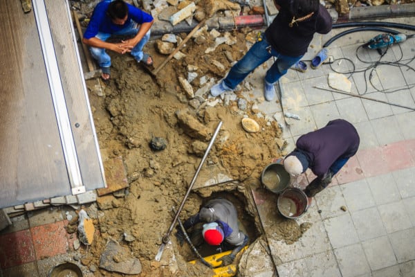
Some standpipe systems are designed to flow as much as 1,250 gallons per minute. We don’t need to talk about how quickly this could fill an Olympic swimming pool, water a golf course, or irrigate an acre of farmland to underscore how fast failure of the water supply serving a standpipe system can turn a nearby lawn into a bog. While most leaks in underground fire protection piping aren’t so obvious, the stakes—both for preventing water damage and controlling fires—remain high.
In this article, we look at how standpipe testing procedures, including flow and hydrostatic tests, can point to a leak underground. You can also read the next installment of this series to learn about the technology contractors use to precisely locate and fix underground standpipe leaks.
If you’re looking for flow or hydrostatic testing equipment, feel free to browse our selection of hydrostatic test pumps, flow test accessories, or flow-testing pitot gauges like the ones discussed here.
Visual inspections aren’t practical for underground fire protection piping
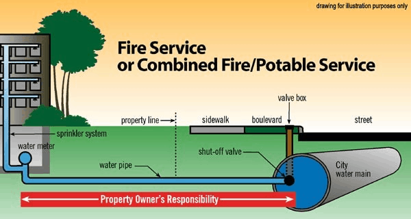
Most standpipe systems draw water from a city water main. While large buildings may have tanks or reservoirs—and while manual dry standpipe systems get water from fire hoses—automatic and semi-automatic standpipe systems often rely on underground pipes for a permanent supply of water.
These pipes are critical, but they’re also particularly hard to inspect. Guidelines from the National Fire Protection Association (NFPA) require building owners to have above-ground pipes checked each year for damage. But underground pipes are unusual in that they’re only inspected when they’re first tested and approved.
NFPA’s standards for the inspection of underground pipes serving standpipe systems are contained in NFPA 25: Standard for the Inspection, Testing, and Maintenance of Water-Based Fire Protection Systems. NFPA 25 doesn’t provide any binding requirements for inspections of existing underground piping. Instead, they offer very brief commentary under the section “7.2.2.2* Underground Piping.”
From the 2017 edition of NFPA 25
A.7.2.2.2 Generally, underground piping cannot be inspected on a routine basis. However, flow testing can reveal the condition of underground piping and should be conducted in accordance with Section 7.3.
Inspectors and code officials take a close look at pipe while it’s still exposed. But after it’s approved and buried, inspections are out—and measurements of flow become the go-to way to unearth problems.
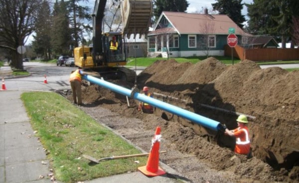
Underground pipes, a kind of fire main, often stay exposed during acceptance tests
The success of most standpipe systems depends on the condition of underground fire protection piping. It’s easiest to spot problems such as leaks during construction, when pipes remain exposed and visible. As such, the earliest tests of standpipe systems look at underground pipes.
For the rules governing most acceptance tests, installers turn to NFPA 14: Standard for the Installation of Standpipe and Hose Systems. But NFPA 14 has surprisingly little to say about underground pipe:
From the 2016 edition of NFPA 14
6.2 Underground Piping. Underground piping shall be in accordance with NFPA 24.
Here, “underground piping” means only buried piping. Any pipes exposed to the air, such as basement-level pipes, don’t fall into this category. NFPA describes that kind of buried pipe as a private fire service main: pipe and fittings that connect a source of water to a fire protection system. For more information, contractors look to NFPA 24: Standard for the Installation of Private Fire Service Mains and Their Appurtenances.
To acceptance test these pipes, NFPA 24 first requires that they be completely flushed. After that, contractors use pressurized water—in a process known as hydrostatic testing—to check for leaks. Leaving pipe trenches open can make spotting leaks much easier.
From the 2019 edition of NFPA 24
10.10.2.2.4* The trench shall be backfilled between joints before testing to prevent movement of pipe.
Open trenches expedite testing but the risk of a fall or cave-in can make a deep trench “an open grave waiting to be filled.” NFPA 24 allows contractors to cover pipe and joints so long as they repair leaks exposed by these tests.
Hydrostatic tests use high water pressure to check underground pipes serving standpipe systems
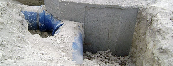
Ideally, the joints that hold underground pipes together remain exposed during acceptance tests. Installers must also consider the condition of thrust blocks, which prevent leaks by fixing joints and fittings in place. These blocks, which often consist of concrete, should fully harden before the tests start.
Installers can then fill the pipes with clean water and add pressure to the system using a hydrostatic test pump. The private fire service main must then hold that water for two hours and the pressure readings must be monitored. Only a small loss of pressure is acceptable.
From the 2019 edition of NFPA 24
10.10.2.2.1* All piping and attached appurtenances subjected to system working pressure shall be hydrostatically tested at gauge pressure of 200 psi (14 bar) or 50 psi (3.4 bar) in excess of the system working pressure, whichever is greater, and shall maintain that pressure at gauge pressure of +/-5 psi (.3 bar) for 2 hours.
Failure of these water-filled, pressurized pipes can cause flooding. But the alternative—air pressure tests—can prove catastrophic. Compressed air can break off and discharge pieces of pipe wall at high speeds, injuring or killing those nearby. Still, some contractors conduct low-pressure air tests, or “pre-tests”, to confirm that pipe joints are properly sealed prior to hydrostatic tests. Tests at 40 pounds per square inch (PSI) or lower can safely expose leaks.
Not all pressure loss indicates a leak. NFPA 24 adds that some materials, such as polybutylene, may expand at first, causing a loss in pressure. As such, it’s important to read the manufacturer’s specifications to make a precise diagnosis.
Acceptable water loss, or “weepage,” increases with system size and pressure
At first, NFPA 24’s rules on the results of pressure tests seem firm on the subject of water loss. During hydrostatic tests, no visible leaks and only a small loss of pressure can occur.
From the 2019 edition of NFPA 24
10.10.2.2.2 Acceptable test results shall be determined by indication of either a pressure loss less than gauge pressure of 5 psi or by no visual leakage.
While some pressure loss is acceptable due to small leaks from underground joints, losses greater than 5 PSI indicate a serious leak in need of repair. But not all water loss constitutes a leak—at least as far as NFPA 24 is concerned. In section 10.10.2.2.6, NFPA 24 provides a formula that specifies how much water can be added to the system to maintain required test pressures.
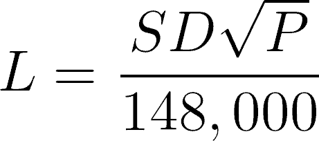
- L = testing allowance (makeup water), in gallons per hour
- S = length of pipe tested, in feet
- D = nominal diameter of pipe, in inches
- P = average test pressure during the hydrostatic test, in pounds per square inch (gauge)
(Note that the metric version of this formula is similar, except the denominator is 794,797, and L is expressed in liters per hour, S in meters, D in millimeters, and P in kPa.)
In this formula, “L” stands for allowable loss, or “weepage.” This means that small droplets of water may leave underground pipes in standpipe systems in limited quantities. The amount grows larger as the length and diameter of pipe increase. Higher pressures also increase how much water underground piping can lose. But it takes a large increase in pressure to make a modest increase in allowable loss. An average pressure of 200 PSI multiplies the allowable loss by about 14, while average pressures of 250 PSI multiply allowable loss by about 16.
Required flow tests can uncover leaks or other issues in underground pipes serving standpipe systems
Hydrostatic tests with a visual inspection are the usual way to detect leaks during acceptance tests. But what about leaks that emerge after the standpipe’s underground pipe is placed in service?
NFPA 25’s rules for testing standpipe systems include regular flow tests for underground equipment, including underground pipes, in section 7.3. We’ve described a basic version of this test in our entry on the pitot tube, a tool made to measure flow. During flow tests, inspectors compare current flow rates with a benchmark—either past measurements or a required rate—to find out if pipes can move water quickly enough.
From the 2017 edition of NFPA 25
7.3 Testing.
7.3.1* Underground and Exposed Piping Flow Tests. Underground and exposed piping shall be flow tested at minimum 5-year intervals.
7.3.1.1 Any flow test results that indicate deterioration of available waterflow and pressure shall be investigated to the complete satisfaction of the authority having jurisdiction to ensure that the required flow and pressure are available for fire protection.
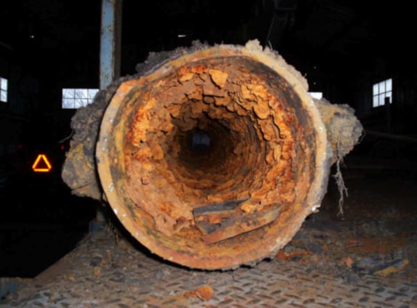
A private fire service main that doesn’t flow water as quickly as it used to may have any number of problems. The NFPA 25 Handbook—a source of more detail on this topic—explains that underground piping and connected fittings often degrade. Rust, debris, garbage, and leaks may all reduce flow rates.
Inspectors can begin to pinpoint the source of the problem using a process called hydraulic gradient analysis. As water moves through a pipe, friction between the pipe’s wall and the water causes a loss in pressure. This phenomenon, known as friction loss, grows more intense as pipes grow longer. By estimating how much pressure new pipe would have—while accounting for friction loss—and looking at current pressures at specific points along underground pipe, contractors can infer which section or sections of pipe may have a leak or blockage.
Fire hydrants may be used to flow test fire service mains for standpipe systems, but other options are available
Some private fire service mains serve more than one fire protection system. When those pipes supply water to a standpipe system and to fire hydrants, flow tests may look something like this:
- A gauge at one hydrant reads the static pressure (the pressure with no water flowing).
- Contractors open hydrants at carefully-chosen points along the main.
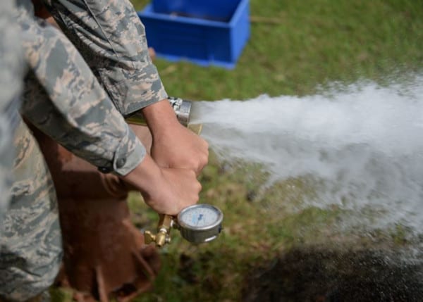
- Pitot tubes measure the pressure of water flowing from open hydrants.
- Contractors convert this pressure (velocity pressure) to flow rates in gallons per minute (GPM).
These flow rates are compared with expected or past flows. If, at a given static pressure, these outlets don’t flow water as quickly as they used to, a leak or blockage may be present.
As NFPA 25 suggests, fire hydrants aren’t necessary for flow tests of underground pipes. If, instead, a pipe runs directly from the water main to the standpipe system, contractors can measure flow rates at other outlets.
From the 2017 edition of NFPA 25
A.7.3.1 Full flow tests of underground piping can be accomplished by methods including, but not limited to, flow through yard hydrants, fire department connections once the check valve has been removed, main drain connections, and hose connections. The flow test should be conducted in accordance with NFPA 291.
Each fire department connection (FDC) features a check valve that lets water flow into—but not out of—the standpipe system. To use an FDC in a flow test, the check valve will need to be removed, bypassed, or disabled (by removing the clapper). Contractors can also use other outlets, such as the main drain or hose connections near the private fire service main.
Tools for flow and pressure tests help contractors take the first steps toward repairs
Low flows or lost pressure can point to serious problems with underground pipe. In part two of this series, we talk about how contractors pinpoint and fix leaks in underground fire protection piping, looking at tools that find leaks without breaking ground and the choices for repairing or replacing damaged pipe.
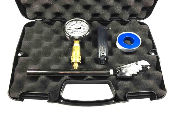
Need tools for hydrostatic or pressure tests? QRFS stocks pumps, gauges, caps, and kits for NFPA 14 and NFPA 25 tests of standpipe systems. Our lightweight pitot gauge kits contain everything needed to measure flow rates wherever water flows, including a gauge with 1 percent full-range accuracy, a quick-disconnect gauge fitting, pitot tubes, and blades.
For more, browse our selection of:
- Flow test accessories
- Hydrostatic test pumps
- Air and water pressure gauges
- Pitot gauge kits and parts
Need more information about standpipe testing procedures or tools? Call us at +1 (888) 361-6662 or email support@qrfs.com.
This blog was originally posted at blog.qrfs.com.

Thank you for this very useful information.
Can I get the leakage formula with (kms) units, please?
Ahmad — The metric formula is found in section 10.10.2.2.6b of NFPA 24 (2019 edition) and is similar in setup to the formula in the blog above. The differences are that the denominator is 794,797 instead of 148,000, and L is expressed in liters per hour, S in meters, D in millimeters, and P in kPa.