

The inspection and maintenance requirements for hoses, hose connections, and system valves
The design and upkeep needs of standpipe systems are outlined in NFPA 14: Standard for the Installation of Standpipe and Hose Systems and NFPA 25: Standard for the Inspection, Testing, and Maintenance of Water-Based Fire Protection Systems, as well as the International Fire Code (IFC) and the International Building Code (IBC).
In the previous two installments of our series, we first introduced standpipe and then the major system components including pipes, fire pumps, water flow alarms, drains, gauges, and fire department connections. This article will look at additional, vital portions of a standpipe: the hoses, hose connections and stations, and various system valves. This guide explains the purpose of these items and serves as a quick reference for the maintenance and inspection expected of life safety contractors and building owners.
This post is part 3 of a 7 part series on standpipe systems:
Part 3: More Standpipe System Components and How to Maintain Them
If you’re looking to buy components for your standpipe system, QRFS offers a range of gauges, hose valves and accessories, pin rack items, fire hose reels, butterfly valves, check valves, and large cabinets. If you’re searching for a test pump to conduct a hydrostatic test, or a flow or flush test on a manual system, feel free to contact us to discuss your test pump needs.

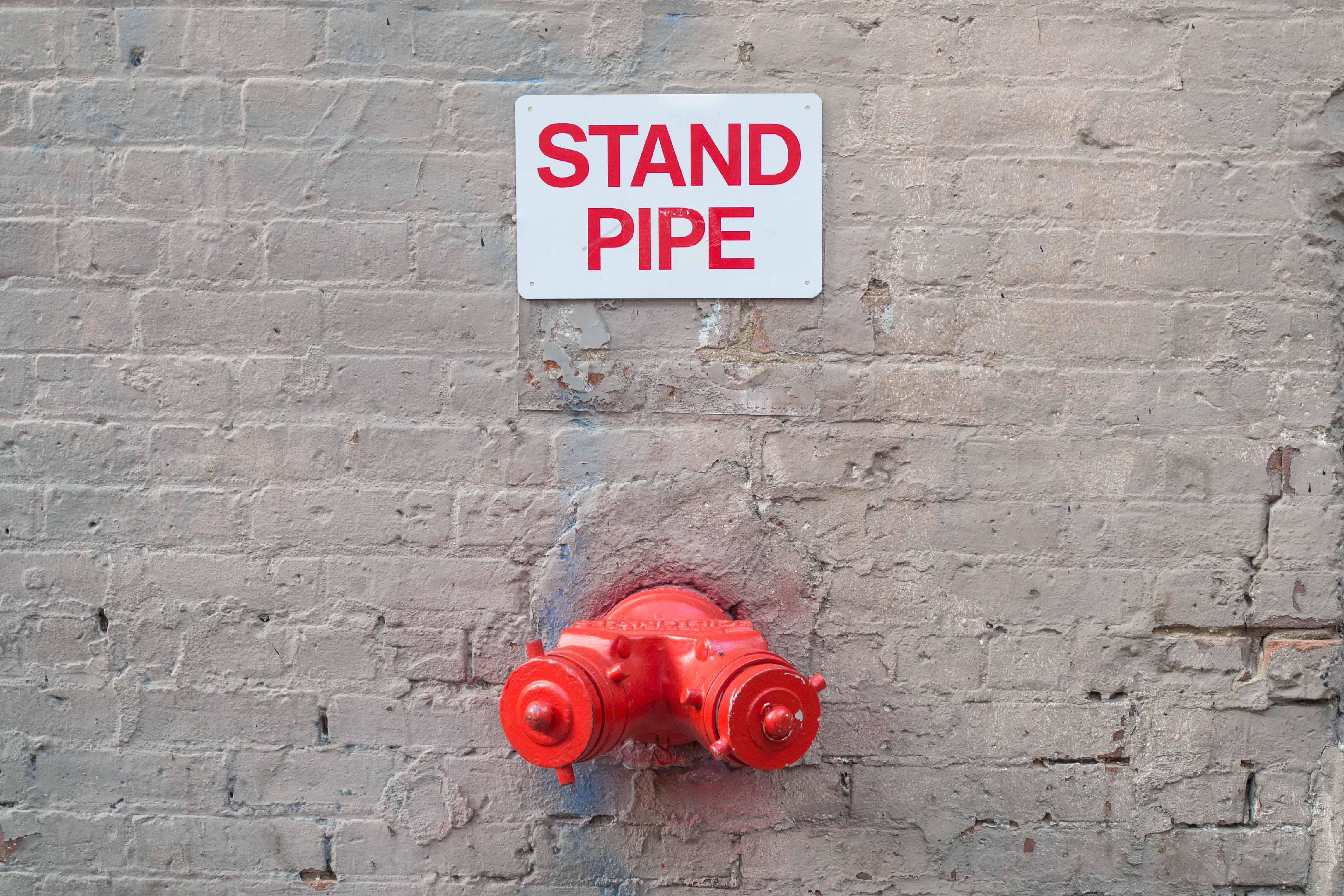
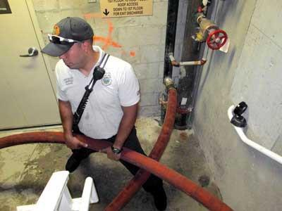
Standpipe in Operation (Image Source)
Hose Valves
As the name makes obvious, hose connections and valves are the various points within a standpipe system where hoses are connected to the piping in order to fight fires. It is essential that there are enough connections, appropriately spaced, to ensure firefighters have complete coverage of a building when they bring in standard hose lengths. To achieve this, NFPA 14 specifies how many connections are required based on their distance from one another, as well as how they should be placed based on access height requirements and potential obstructions.
From the 2016 Edition of NFPA 14:
|
7.3.1.1 Hose connections and hose stations shall be unobstructed and shall be located not less than 3 ft. (0.9 m) or more than 5 ft. (1.5 m) above the floor.
7.3.1.1.1 This dimension shall be measured from the floor to the center of the hose valve.
7.3.1.2 The hose connection shall not be obstructed by any closed or open stairwell door(s) or other objects on the landing.
|
Otherwise, the number and size of hose connections depend on the class of system they serve:
- In Class I systems, 2.5” hose connections must be no longer than a travel distance of 200’ apart in sprinklered buildings and 130’ apart in non-sprinklered buildings, and they must be present in each exit passageway (except in covered mall buildings). In addition, they are required at horizontal exits (these are junctures to different parts of the same floor, often separated by a fire-rated door), and exit stairwells. Note that section 905.4 of the International Building Code contains additional requirements for the placement of hose connections, so find out whether your local authority having jurisdiction (AHJ) has adopted the IBC.
- In Class II systems, there must be enough hose stations to ensure “that all portions of each floor” of the building are within 130’ of a hose station with a 1.5” hose, and within 120’ of a station with less than a 1.5” hose.
- The requirements for Class III systems vary. The system must have both 2.5” and 1.5” connections. If a building is protected by an automatic sprinkler system, hose stations are not required if the 2.5” hose connections have a reducer to 1.5” and a cap with a chain, and the travel restrictions for Class II systems don’t apply. Otherwise, the required placement of connections follows the respective requirements for Class I sprinklered or non-sprinklered buildings above.
Inspections and maintenance required for hose connections:
There are two sets of inspections for hose connections and hose valves listed in NFPA 25, to be conducted annually and quarterly, respectively:
From the 2017 Edition of NFPA 25:
|
6.2.3.1 Hose connections shall be inspected annually for the following conditions:
(1) Valve cap(s) missing or damaged
(2) Fire hose connection damaged
(3) Valve handles missing or damaged
(4) Cap gaskets missing or deteriorated
(5) Valve leaking
(6) Visible and physical obstructions to hose connections
(7) Pressure restricting device missing
(8) Manual, semiautomatic, or dry standpipe valve does not operate smoothly
(9) Valve threads damaged
13.6.1.1 Hose valves shall be inspected quarterly to verify that the valves are in the following condition:
(1) Hose caps are in place and not damaged.
(2) Hose threads are not damaged.
(3) Valve handles are present and not damaged.
(4) Gaskets are not damaged or showing signs of deterioration.
(5) No leaks are present.
(6) Valves are not obstructed or otherwise not capable of normal operation.
|
An important note on hose connections: There is a standardized thread that is intended to make it easy for manufacturers to create hose connections that work with most fire department equipment, while also making it simple for building owners to purchase the right components. But not all fire departments use these standard threads – over 100 fire departments use non-standard threads as of 2016. Thus, you must make sure that the couplings on your hose connections are specifically suited for your local fire department’s equipment. (NFPA 14: 11.3.1)

Pin Rack Unit in Wall (Image Source)
Hose and Hose Stations
Obviously, all Class II and some Class III standpipe systems have pre-attached hoses on site. In a Class II system, this 1.5” hose must be lined, and it can either be a collapsible hose that is stored on a rack or a non-collapsible hose placed on a reel. Hose stations can be stored within cabinets that must be large enough so that there is at least 2” of space between any part of the cabinet and the hose valve. These cabinets must be clearly marked with signage, use tempered glass, and, if a break-glass cover is used, the device used to break the glass must be tethered to the cabinet with a tether that isn’t long enough to break any other nearby glass.
Inspections and maintenance required for hoses and hose stations:
Hoses, hose nozzles, hose storage devices, and cabinets all require annual inspections which take on added importance in a Class II system, which needs hose stations to work as the primary method of fighting a fire. Because on-site hose stations are often infrequently inspected and poorly maintained, these systems (Class II) or components of systems (any on-site, 1.5” hose stations in Class III) are considered less reliable than equipment in other systems. This unreliability, coupled with the fact that authorities have become concerned about non-trained personnel trying to fight a fire, have resulted in Class II systems falling out of favor for new standpipe installations. In addition, fewer Class III systems now have onsite hose stations that any occupant can access and use. If your building has hose stations – especially if it is a Class II system that relies on them – make sure to stay on top of these four annual inspections to make sure they work:
From the 2017 Edition of NFPA 25:
|
6.2.5.1 Hose shall be inspected annually for the following conditions as required by NFPA 1962:
(1) Mildew, cuts, abrasions, and deterioration
(2) Couplings hose threads damaged
(3) Gaskets missing or deteriorated
(4) Incompatible threads on coupling
(5) Hose not connected to hose rack nipple or valve
(6) Hose test outdated
6.2.6.1 Hose nozzles shall be inspected annually for the following conditions:
(1) Hose nozzle missing
(2) Gasket missing or deteriorated
(3) Obstructions
(4) Does not operate smoothly
6.2.7.1 Hose storage devices shall be inspected annually for the following conditions:
(1) Difficult to operate
(2) Damaged
(3) Visible or physical obstruction
(4) Hose improperly racked or rolled
(5) Nozzle clip not in place and nozzle not correctly contained
(6) Hose rack enclosed in cabinet not swinging out at least 90 degrees
6.2.8.1 Cabinets shall be inspected annually for the following conditions:
(1) Overall for corroded or damaged parts
(2) Difficult to open
(3) Cabinet door not opening fully
(4) Door glazing cracked or broken
(5) Lock on break glass–type cabinet not functioning properly
(6) Glass break device missing or not attached
(7) Not properly identified as containing fire equipment
(8) Visible or physical obstructions
(9) All valves, hose, nozzles, fire extinguishers, and so forth, easily accessible
|
Standpipe System Valves
In addition to hose valves, various standpipe systems commonly have control valves, preaction and deluge valves (in semiautomatic dry standpipe systems), pressure-reducing valves (automatic and semiautomatic systems), and check valves.
Control valves
Control valves control the flow of water to different portions of a standpipe system. They are required in three areas: at the connections to water supplies, at areas where portions of the standpipe need to be isolated, and at the connections to sprinkler systems. In each case, the control valve serves the purpose of cutting off the water to the system (or a portion of the system), so that repairs can be made. Their different locations allow certain portions of a system to be taken out of service while other areas remain operational in the event of an emergency. There are two types of control valve:
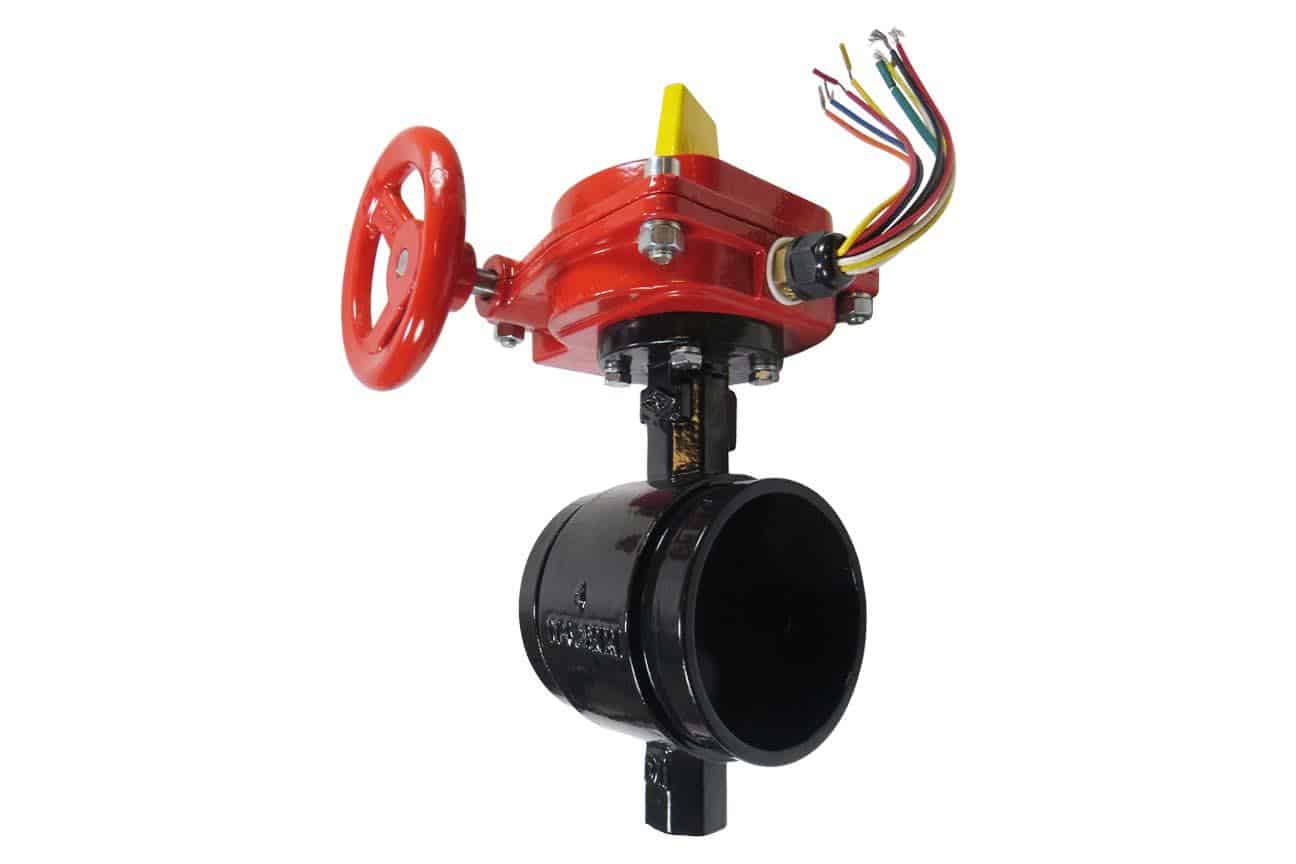
- Outside screw and yoke (OS&Y) valves have a threaded stem that pops out of the valve to indicate that it is open.
- Butterfly valves use an internal gate to block water. The gate is attached to a visible, external paddle. When this paddle runs parallel the pipe, you know that the valve is open; a perpendicular orientation to the pipe means it’s closed.
Inspection requirements for control valves can be weekly, monthly, and quarterly based on whether they are locked, continuously supervised by personnel, or have electrical supervisory devices in place. These three measures reduce the risk of a control valve being accidentally closed or tampered with, which could render the system or a portion of the system inoperable during a fire. Most AHJs require control valves to be secured or electrically monitored.
From the 2017 Edition of NFPA 25:
|
13.3.2.1 All valves shall be inspected weekly.
13.3.2.1.1 Valves secured with locks or supervised in accordance with applicable NFPA standards shall be permitted to be inspected monthly.
13.3.2.1.2 Valves that are electrically supervised shall be permitted to be inspected quarterly.
13.3.2.1.3 Control valve supervisory alarm devices shall be inspected quarterly to verify that they are free of physical damage.
13.3.2.1.4 After any alterations or repairs, an inspection shall be made by the property owner or designated representative to ensure that the system is in service and all valves are in the normal position and properly sealed, locked, or electrically supervised.
13.3.2.2* The valve inspection shall verify that the valves are in the following condition:
(1) In the normal open or closed position
(2) * Sealed, locked, or supervised
(3) Accessible
(4) Post indicator valves (PIVs) are provided with correct wrenches
(5) Free from external leaks
(6) Provided with applicable identification
|
Pressure-restricting valves
Pressure-restricting valves are used to reduce the pressure coming out of hose connections on the lower floors of a tall building. Because greater pressure must be applied to fight gravity to meet demand on high floors, the greater pressure on lower floors may need to be limited to make water flow manageable. These valves come in two varieties:

- Direct acting pressure valves “take a certain amount of pressure away from the water as it moves through the valve … The pressure drop across the device is the same regardless of the incoming pressure.” (Isman, pp. 174-175)
- Pilot-operated valves adjust “the pressure drop so that the pressure is constant on the downstream side regardless of incoming pressure.” (Isman, p. 174)
Inspection requirements for pressure-restricting valves:
Pressure reducing valves on hose stations have annual inspection requirements, whereas inspections of pressure-restricting valves used at hose connections are quarterly.
From the 2017 Edition of NFPA 25:
|
Pressure-reducing valves at hose stations:
13.5.2.1 All devices shall be inspected annually to verify the following:
(1) The handwheel is not broken or missing.
(2) The outlet hose threads are not damaged.
(3) No leaks are present.
(4) The hose adapter and the cap are not missing.
Pressure-reducing valves at hose connections:
13.5.1.1 All valves shall be inspected quarterly to verify that the valves are in the following condition:
(1) In the open position
(2) Not leaking
(3) Maintaining downstream pressures in accordance with the design criteria
(4) Handwheels installed and unbroken
|
Preaction and deluge valves (semiautomatic dry systems only)
Preaction and deluge valves are exclusively used in semiautomatic dry standpipe systems. These valves are “tripped” in the event of an emergency, allowing water to flood the usually dry pipes in the rest of the system. The valves are activated by an electrical signal sent from a pull station or button, and they must also have a separate mechanical or hydraulic means of flooding the system as a back-up.
Inspection requirements for preaction and deluge valves:
From the 2017 Edition of NFPA 25:
|
13.4.3.1.1/13.4.4.1.1 Valve enclosures for preaction/deluge valves subject to freezing shall be inspected daily during cold weather to verify a minimum temperature of 40°F (4.0°C).
13.4.3.1.1.1/13.4.4.1.1.1 Valve enclosures equipped with low-temperature alarms shall be inspected weekly.
13.4.3.1.2/13.4.4.1.2 Low-temperature alarms, if installed in valve enclosures, shall be inspected annually at the beginning of the heating season to verify that they are free of physical damage.
13.4.3.1.3/13.4.4.1.3 The preaction/deluge valve shall be externally inspected monthly to verify the following:
(1) The valve is free from physical damage.
(2) All trim valves are in the appropriate open or closed position.
(3) The valve seat is not leaking.
(4) Electrical components are in service.
|
In addition, “internal inspection of valves that can be reset without removal of a faceplate” should be conducted every 5 years, as well as inspection of “strainers, filters, restricting orifices, and diaphragm chambers unless tests indicate a greater frequency is necessary.” (13.4.4.1.4.1, 13.4.4.1.5)
There are also two types of fire pump relief valves that regulate pressure – circulation relief valves and main pressure relief valves – which are only installed on automatic and semiautomatic standpipe systems. These valves are designed to stop engine overspeed (preventing engine damage) as well as to prevent overpressure in these standpipe systems. These valves must be inspected during any fire pump flow test (see Table 8.1.1.2 in our previous installment of this series).
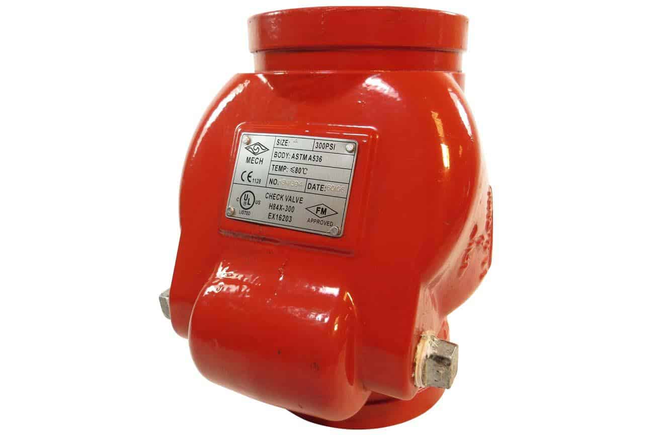
Check valves
A check valve is any valve that makes sure that water flows in only one direction. In standpipe systems, check valves are required at the fire department connection (FDC) to avoid spillage when a hose is disconnected, as well as at the connections to any water supply. In a sprinklered building, the latter variety prevents the highly-pressurized water in the standpipes from entering the lower-pressure sprinkler system. In addition, a specific check valve called a backflow preventer is needed to keep any stagnant water in a sprinkler or standpipe system from flooding back into (and contaminating) the city water supply.
Inspection and maintenance requirements for check valves:
From the 2017 Edition of NFPA 25:
|
13.4.2.1 Inspection. Valves shall be inspected internally every 5 years to verify that all of the valve’s components operate correctly.
13.4.2.2 Maintenance Internal components shall be cleaned, repaired, or replaced as necessary in accordance with the manufacturer’s instructions.
|
Dry pipe valves (automatic dry standpipe systems only)
Dry pipe valves are only present in automatic dry standpipe systems. They serve as the junction between the water supply and the highly-pressurized air in the pipes of these system, which holds the dry pipe valve closed until the air pressure drops. A loss of air pressure trips the valve and floods the system with water.
Inspection requirements for dry pipe valves:
From the 2017 Edition of NFPA 25:
|
13.4.5.1.3 The dry pipe valve shall be externally inspected monthly to verify the following:
(1) The valve is free of physical damage.
(2) All trim valves are in the appropriate open or closed position.
(3) The intermediate chamber is not leaking.
|
Similarly, only automatic dry systems require a specific relief valve to be installed at “the air fill connection to prevent the system from putting too much air in the standpipe system.” (Isman, p. 120)
To be continued: The Complete Guide to Standpipe Systems
This concludes part three of our review of standpipe systems, rounding out the major system components and their upkeep requirements. In the next installment of this series, we discuss the regular NFPA testing requirements that ensure that a standpipe system works during a fire.
If you’re looking to buy components for your standpipe system, QRFS offers a range of gauges, hose valves and accessories, pin rack items, fire hose reels, butterfly valves, check valves, and large cabinets. If you’re searching for a test pump to conduct a hydrostatic test, or a flow or flush test on a manual system, feel free to contact us to discuss your test pump needs.
Get Standpipe System Components Here
If you have any questions about standpipes or need help finding an item, add a comment below, give us a call at 888.361.6662, or fill out our contact form and we’d be happy to assist.
View Other Posts in this Series on Standpipe Systems
<< Standpipe Systems (Part 2): Standpipe System Components and How to Maintain Them |
Standpipe Systems (Part 4): Acceptance Testing and Ongoing System Maintenance >> |
Additional Sources:
- Isman, Kenneth E. Standpipe Systems for Fire Protection. Springer International Publishing.
- Alpert, Rick. “Standpipe Systems: Design and Installation Requirements.” Sprinkler Age. https://sprinklerage.com/standpipe-systems-design-installation-requirements/
- “All FMs need to know about standpipes for firefighting.” FMLink. https://fmlink.com/articles/all-fms-need-to-know-about-standpipes-for-fire-fighting/
- International Building Code 2015 (IBC 2015)
- NFPA 14: Standard for the Installation of Standpipe and Hose Systems (2016)
- NFPA 25: Standard for the Inspection, Testing, and Maintenance of Water-Based Fire Protection Systems
