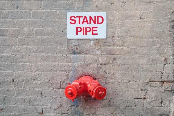
Standpipe systems rely on a vast array of components, from fire department connections to electronic monitoring equipment
Standpipe systems have numerous components, each of which needs to be properly installed, inspected, and maintained to ensure it works in the event of an emergency.
The placement and upkeep requirements of standpipe components are outlined in NFPA 14: Standard for the Installation of Standpipe and Hose Systems and NFPA 25: Standard for the Inspection, Testing, and Maintenance of Water-Based Fire Protection Systems, as well as the International Fire Code (IFC) and the International Building Code (IBC). Ultimately, however, the Authority Having Jurisdiction (AHJ), usually a state or local government agency, has the final say on the exact requirements.
In part one of our standpipe series, we provided an overview of standpipe systems, including the five types and three classes, and how each one functions. This article examines the major individual components of standpipe systems, along with their installation, inspection, and maintenance requirements. Our aim is to simplify this guidance for both contractors and building owners.
This post is part 2 of a 7 part series on standpipe systems:
Part 1: Fire Protection Standpipe System Overview and Introduction to NFPA 14
Part 2: Standpipe System Components and How to Maintain Them
Part 3: More Standpipe System Components and How to Maintain Them
Part 4: Acceptance Testing and Ongoing System Maintenance
Part 5: Maintenance Testing of Standpipes (Continued)
Part 6: Maintenance Testing for Automatic and Semiautomatic Dry Standpipes
Part 7: Standpipe Signs and Markings
Are you looking to buy components, accessories, or testing equipment for your building’s standpipe system? If so, feel free to skip directly to our selection of hose valves and accessories, fire department connections, or hydrostatic test pumps. Or just use the search bar at the top of the page to find the exact fire protection products you need.
Basic Components of Standpipe Systems
While each system can vary, a standpipe generally consists of an interconnected series of pipe, pumps, valves, alarms, drains, and fire department connections. Over the course of this article and the next, we’ll discuss each of these components in detail including maintenance and regulatory requirements. So, without further ado …
Pipe
The most extensive component of a standpipe system is the network of pipes which carries water throughout the building. The National Fire Protection Association (NFPA) specifies different requirements for the material used in underground pipes and above-ground pipes.
Underground pipes are defined as those “buried in soil” and they must be made of lined ductile iron, cement, copper, brass, or plastic. Steel pipes are not permitted underground, as they tend to corrode quickly in the soil.
Above-ground pipes include those found in underground basements and garages, as well as the pipes that travel throughout the rest of the building. They can be composed of steel, ductile iron, or copper, with steel being the most popular choice. This metal is often chosen because it is sturdier than ductile iron and less expensive (and less subject to theft) than copper.
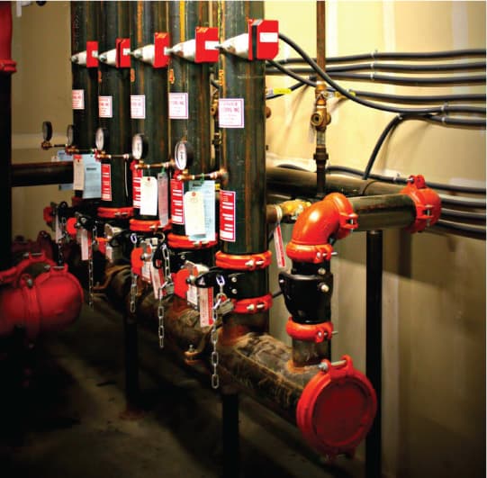
The diameter and thickness of the pipe used in standpipe systems are determined by specific hydraulic calculations about required system pressure and demand based on the size and height of the building. That said, NFPA 14 requires that standpipes be at least 4” (100 mm) in size, whereas pipes that are part of a combined standpipe/sprinkler system need to be at least 6” (150 mm).
Inspection and maintenance required for piping
From the 2017 Edition of NFPA 25
6.2.4.1 Piping shall be inspected annually for the following conditions:
(1) Damaged piping
(2) Damaged control valves
(3) Missing or damaged pipe support device (i.e., missing or damaged hanger or seismic brace)
(4) Damaged supervisory signal initiating device
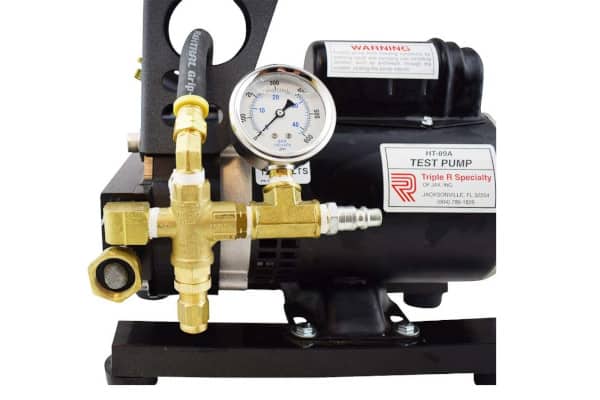
Inspection of standpipe systems should be conducted annually. It is very difficult, if not impossible, to inspect underground piping. The damage that may result in leaks is not always apparent in above-ground piping in manual dry, semiautomatic dry, and automatic dry standpipe systems, since they are not always filled with water. An initial and five-year hydrostatic test can identify obvious leaks in above-ground piping in dry systems as well as hidden leaks in the underground portions of any system.
If any of the above issues are spotted during an inspection, NFPA 25 requires that “where any deficiency is noted, the appropriate corrective action shall be taken.” This general requirement applies to all of the inspections for every component of a standpipe system. Though the 2011 edition of NFPA 25 began allowing for classifying problems in three tiers—as an impairment, a critical deficiency, or a non-critical deficiency—if an inspection spots something, fix it ASAP.
Fire Pumps
Fire pumps are the on-site mechanism that supplies pressurized water for automatic and semiautomatic standpipe systems. Manual standpipe systems do not need them since the fire department supplies the water and pressure from trucks when firefighters arrive on the scene. The right fire pump for a standpipe system depends on the pump’s size and flow capacity relative to the system demand of the standpipe it will serve. Most standpipes have a system demand of 750, 1,000, or 1,250 gallons per minute (GPM), and a pump can be used to supply a system that has a demand of 100% to 150% of the pump’s flow capacity.
For example, a fire pump that is rated at 500 GPM can be used for a standpipe with a system demand of 750 GPM, though a pump with an exact rating of 750 GPM is also commonly used. Using pumps with a greater flow rate than the system demand isn’t advisable for two reasons: It has the potential to apply too much pressure to the system, and larger pumps are more expensive.
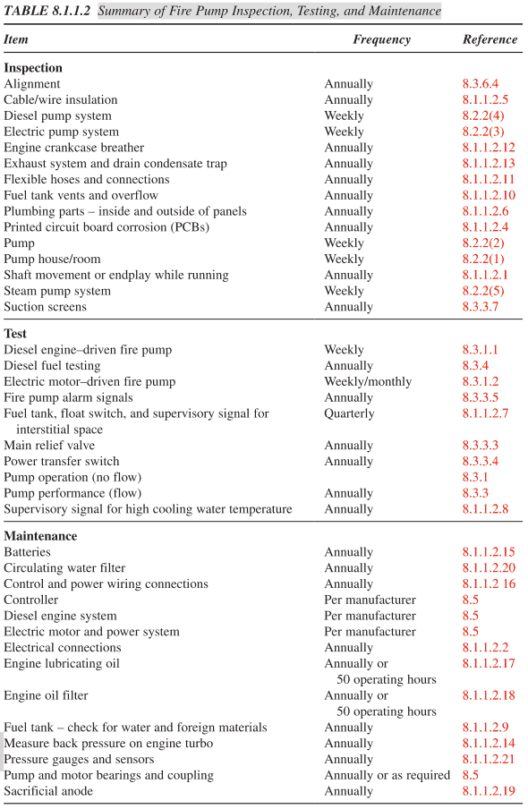
The requirements for regular inspection and maintenance of fire pumps are extensive and exhaustively detailed in Chapter 8 of NFPA 25. Table 8.1.1.2 below lists all of the necessary actions:
For more information on the annual (and beyond) requirements for fire pump testing, read our two-part series: “The Fire Pump Flow Test” and “Fire Pump Component Testing.”
Waterflow Alarms
Every standpipe system (with the exception of the manual dry variety) requires that a water flow alarm device is installed in a portion of the piping between the water supply and the initial hose connection. This alarm sounds to provide notice that the system is engaged during a fire. It also gets the attention of personnel who can assess whether there is indeed an emergency; if not, these alarms could prevent water damage in a compromised system.
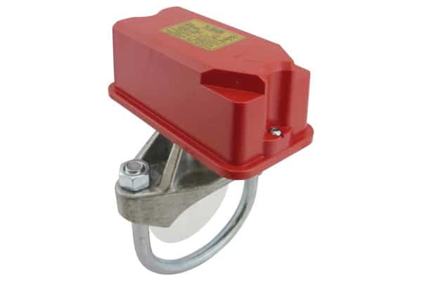
From the 2017 Edition of NFPA 25
13.2.6.1.1 Mechanical waterflow alarm devices shall be inspected quarterly to verify that they are free of physical damage.
13.2.6.2.1 Vane-type, paddle-type, and pressure switch-type waterflow alarm devices shall be inspected quarterly to verify that they are free of physical damage.
To learn more about which flow-sensing devices are appropriate for your standpipe system, check out “Flow Switches vs. Pressure Switches in Fire Protection.”
Standpipe Drains
Some form of drain is required on every standpipe system, and multiple drains are often needed. All systems must have a main drain on the water supply piping which allows the system to be drained and for technicians to conduct testing. If portions of the system are isolated and will not drain via the main drain, appropriate auxiliary drains are required. Learn all about fire protection system drains here.
For standpipe drains, all inspection and maintenance requirements are fulfilled during annual main drain testing. That said, routine inspection is required to ensure that signage is present to identify and locate drains.

Gauges
Gauges are required in numerous portions of standpipe systems. They provide a pressure reading during testing conditions and assess the normal operating pressure of the system. Gauge locations include:
- At the top of each standpipe (required)
- At every water supply connection (required)
- Upstream or downstream of any master pressure regulating assembly (required)
- Above and below each alarm check valve, dry pipe valve, deluge valve, backflow preventer, or system riser check valve (required)
- At hose stations which have a pressure-reducing valve (optional)
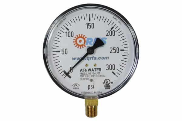
Due to the importance of monitoring your standpipe system, maintaining the gauges is especially critical.
From the 2017 Edition of NFPA 25
13.2.7.1.1* Gauges shall be inspected monthly to verify that the gauge is operable and not physically damaged.
13.2.7.1.2 Gauges monitoring water pressure shall be inspected quarterly to verify that normal water supply pressure is being maintained.
13.2.7.1.3 Gauges monitoring air or nitrogen pressure shall be inspected monthly to verify that normal air or nitrogen pressure are being maintained.
13.2.7.1.3.1 The gauge on the quick-opening device, if provided, shall indicate the same pressure as the gauge on the system side of the dry pipe valve.
13.2.7.1.3.2 Where air pressure supervision is connected to a constantly attended location, gauges shall be inspected quarterly.
13.2.7.1.4* For dry pipe or preaction systems protecting freezers with an air pressure gauge(s) on the air line(s) between the compressor and the dry pipe or preaction valve, the air pressure gauge near the compressor shall be compared monthly to the pressure gauge above the dry pipe or preaction valve.
13.2.7.1.4.1 When the gauge near the compressor is reading higher than the gauge near the dry pipe valve, the air line in service shall be taken out of service and the alternate air line shall be opened to equalize the pressure.
13.2.7.1.4.2 An air line taken out of service in accordance with 13.2.7.1.4.1 shall be internally inspected, removed of all ice blockage, and reassembled for use as a future alternate air line.
13.2.7.2* Gauges shall be replaced every 5 years or tested every 5 years by comparison with a calibrated gauge.
13.2.7.3 Gauges not accurate to within 3 percent of the full scale shall be recalibrated or replaced.
Fire Department Connection
Requirements for fire department connections vary with building size and other factors
The fire department connection (FDC) is an essential component of manual wet and manual dry systems, which will not work without firefighters supplying water and pressure to the system. That said, FDCs are still required in all Class I and Class III systems, even those with onsite fire pumps that serve the express purpose of supplying pressurized water. The rationale for requiring FDCs in these systems is simple: If a fire pump malfunctions during an emergency, the FDC provides a back-up.
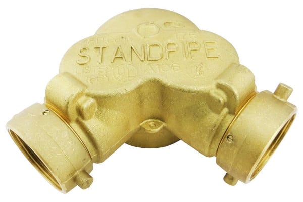
In order to ensure adequate pressure to all portions of a building—especially in very tall structures—many standpipe systems are segmented into separate vertical zones. Each of these zones requires at least one FDC (NFPA 14: 7.12.2.1), though NFPA also stipulates that “high-rise buildings shall have at least two remotely located fire department connections for each zone.” (7.12.2)
The upper floors in extremely tall buildings are an exception to this rule if a fire truck accessing an FDC cannot supply adequate water and pressure to the elevation (7.12.1.1). NFPA requires that these high floors have “an auxiliary means of supply in the form of high-level water storage with additional pumping equipment or other means acceptable to the AHJ (authority having jurisdiction).” (7.9.3)
The pumping ability of fire department vehicles varies, so a standpipe must be designed with the capabilities of local firefighters in mind. Generally speaking, most fire departments can supply enough water and pressure through the FDC to reach floors that are between 200 to 350 feet above the street.
FDCs vary in their design, number of inlets, inlet size, and more
Each FDC must also have enough individual 2 1/2″ inlet connections to meet the flow demand of the building: one for every 250 gallons per minute (GPM) of demand. Most buildings with more than one stairwell require an FDC with at least three inlet connections (four are commonly used), and these connections must match the size and specific hose connections that are employed by the local fire department, whether they are 2 1/2″ connections with traditional threads or 4″ or 5″ inlets using Storz connections (aka large-diameter threadless couplings).
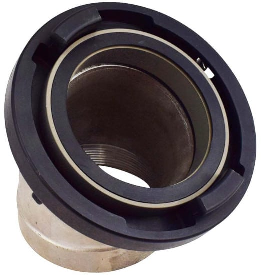
Storz connections were once rare in the US, but they are becoming more popular, as they make it easier to connect a hose. Also, note that San Francisco and New York commonly use a 3” traditional threaded connection, so make sure that your FDC inlets match the needs of your local fire department.
FDCs can be:
- Flush against the side of a building
- Exposed: The heads protrude outward from the side of the building at opposite angles (this design is known as a “Siamese connection”)
- Freestanding: A pipe juts upward from the ground and the inlet connections sit at the top of the pipe.
Signage and proper placement are critical for standpipe FDCs
Accessibility and visibility determine which FDC design should be used.
From the 2016 Edition of NFPA 14
6.4.5.1 Fire department connections shall be visible and recognizable from the street or nearest point of fire department apparatus accessibility or on the street side of buildings.
6.4.5.1.1 Fire department connections shall be located and arranged so that hose lines can be attached to the inlets without interference from nearby objects, including buildings, fences, posts, landscaping, vehicles, or other fire department connections.
For example, a flush FDC on the side of a building that is blocked by shrubs will be neither visible nor accessible, whereas a freestanding version set forward from the building would work. A connection that is walled off from the street by a fence or one that is blocked by a parked car also might limit access by fire trucks.
In addition, the placement and design of an FDC should take into account the path along which any attached hose will run; this path should not block any exits, potentially impeding occupants who are trying to escape from a fire.
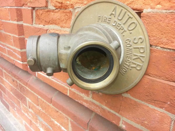
Finally, each FDC must be clearly labeled with signage and each inlet connection must have break caps or plugs that protect the opening from any obstruction, such as vandalism or debris that could find its way inside the inlet and block the flow of water. Failing to have these caps installed is one of the most commonly cited code violations. Sometimes they break or contractors fail to install them in the first place, but thievery is a likelier cause.
There are plastic or aluminum caps that firefighters can easily break open in an emergency, and screwable brass, plastic, or aluminum plugs that are secured by a chain. Brass plugs are more durable, but thieves may target them because of their value. Be sure to consider the risk of caps or plugs being stolen when choosing a solution that works for your building. If a thief takes them, you could be out the cost of a new cap or plug and the possible fine associated with a code violation.
Important note for FDCs in New York and San Francisco:
Fire departments in New York and San Francisco are the only authorities that commonly use 3″ hose connections; thus, FDC inlets in these cities and the plugs that cover them must be compatible with the local fire department—and you should check with your authority having jurisdiction no matter where you live.
In addition, as of 2010, FDC caps or the entire apparatus must be color-coded in New York. Inlets that access a standpipe system must be red, those that access a sprinkler system must be green, and those that connect to a combined standpipe/sprinkler system are yellow. The colors enable firefighters to quickly identify the nature of an FDC in the event of an emergency.
Need caps in New York or San Francisco? You can buy 3″ plugs on QRFS either painted or unpainted.
Most FDCs require quarterly inspection with an annual interior inspection—if caps remain in place. The corrective measure for any issue is to repair or replace “as necessary in accordance with the manufacturer’s instructions” and to essentially remove any obstructions that would keep the FDC from doing its job.
From the 2017 Edition of NFPA 25
13.8.1 Fire department connections shall be inspected quarterly to verify the following:
(1) Fire department connections are visible and accessible.
(2) Couplings or swivels are not damaged and rotate smoothly.
(3) Plugs or caps are in place and undamaged.
(4) Gaskets are in place.
(5) Identification signs are in place.
(6) Check valve is not leaking.
(7) Automatic drain valve is in place and operating properly.
(8) Fire department connection clapper(s) is in place and operating properly.
(9) * Interior of the connection is inspected for obstructions.
(10) Visible piping supplying the fire department connection is undamaged.13.8.2 Interior inspections shall be conducted annually if approved locking caps or locking plugs are installed.
Components large and small allow standpipe systems to deliver water when it’s needed most
This concludes part two of our review of standpipe systems, introducing the major system components and their upkeep requirements. In the next installment of this series, we review more components of various standpipe systems, including the numerous valves, hoses, hose connections, and hose stations needed.
QRFS offers a range of components for standpipe systems, including:
- Hose valves and accessories
- Fire department connections and accessories
- Flow and pressure switches
- hydrostatic test pumps
Browse our full selection of standpipe gear.
If you have any questions about standpipes or need help finding an item simply add a comment below, give us a call at (888) 361-6662 or email support@qrfs.com.
View Other Posts in this Series on Standpipe Systems
Part 1: Fire Protection Standpipe System Overview and Introduction to NFPA 14
Part 2: Standpipe System Components and How to Maintain Them
Part 3: More Standpipe System Components and How to Maintain Them
Part 4: Acceptance Testing of Standpipes
Part 5: Maintenance Testing of Standpipes (Continued)
Part 6: Maintenance Testing for Automatic and Semiautomatic Dry Standpipes
Part 7: Standpipe Signs and Marking
Additional Sources
- Isman, Kenneth E. Standpipe Systems for Fire Protection. Springer International Publishing.
- Trumbature, Mike. “SETTING FIRE PUMP MAIN RELIEF VALVES.” LinkedIn. https://www.linkedin.com/pulse/setting-fire-pump-main-relief-valves-mike-trumbature
- Alpert, Rick. “Standpipe Systems: Design and Installation Requirements.” Sprinkler Age. https://sprinklerage.com/standpipe-systems-design-installation-requirements/
- Avsec, Robert. “The fire department connection: A primer.” Fire Rescue 1. https://www.firerescue1.com/Firefighter-Training/articles/249974018-The-fire-department-connection-A-primer/
- International Building Code 2015 (IBC 2015)
- NFPA 14: Standard for the Installation of Standpipe and Hose Systems (2016)
- NFPA 25: Standard for the Inspection, Testing, and Maintenance of Water-Based Fire Protection Systems
- “All FMs need to know about standpipes for firefighting.” FMLink. https://fmlink.com/articles/all-fms-need-to-know-about-standpipes-for-fire-fighting/
- Song, Elizabeth and Lizardo, Michael. “Why Are Siamese Connections Colored?” Decoder. https://www.decodernyc.com/siamese-connections-color-coded-fdny/
This article was originally posted on blog.qrfs.com on January 11, 2018, and updated on August 30, 2019. Like what you read? Check out the rest of our Thoughts on Fire.


